Pavement deflection full-field laser detection method and system

A laser detection and road surface deflection technology, applied in the direction of roads, roads, road repair, etc., can solve the problems of difficult span, can not be used as standard measurement, unclear measurement base point, etc., to achieve reliable measurement benchmark and improve measurement performance. , the effect of high measurement accuracy

Active Publication Date: 2014-03-19
TECH TRANSFER CENT CO LTD NANJING UNIV OF SCI & TECH
View PDF7 Cites 16 Cited by
  • Summary
  • Abstract
  • Description
  • Claims
  • Application Information

AI Technical Summary

Problems solved by technology

[0005] 2. The current situation and existing problems of the existing pavement deflection detection system
[0008] However, there are still many problems with the Beckman beam method: a) The problem of the measurement reference: the measurement reference is actually the fulcrum of the lever beam, to ensure that it will not be affected by the loading and deformation of the road surface during the measurement process. The deflection radius
[0010] In order to solve the problem that the fulcrum of the semi-rigid pavement with a large deflection basin is still within the influence of deflection deformation, it is still not sensitive enough to read rigid or winter deformation in the micron-level road surface, and the laser light can be used instead of the measuring arm. For sufficiently long-distance measurement, using laser technology such as laser diffraction principle or high-resolution CCD positioning principle, the measurement accuracy can reach the micron level, but this method is still an improvement on the basis of the Beckman beam, lengthening the length of the measuring arm, However, the sensitive road surface deformation still uses the same mechanical contact head as the Beckman beam to sense the road surface displacement. It is still a low-speed manual measurement, point-by-point measurement rather than a full-field three-dimensional technology.
[0011] 3) Automatic deflection meter method. With the rapid development of expressways, artificial static deflection measurement methods and equipment are far from meeting the requirements. An automatic deflection meter based on the principle of moving a Beckman beam with a vehicle-mounted short arm has been developed. Automatically grab and place the position of the Beckmann beam to the wheel gap, and measure the deflection value, realizing the vehicle-mounted intelligent automatic measurement, but the measurement speed is still only 4 km / h, and the arm length of the measuring beam is still relatively short, generally within two meters. Because of the deflection radius of the expressway, it obviously cannot be used as a standard measurement
[0012] 4) The FWD method is currently the most widely used equipment method. Based on the pulse impact loading of the falling hammer on the road surface, multiple speed sensor beams are used to contact the road surface to measure the deformation speed and time of the road surface, and then calculate the deflection curve. Obviously, there is also a measurement base point Unclear, the beam span is smaller than the deflection radius, and the measurement speed is still only 4 km / h, the impact load is uncertain, and obviously cannot be used as a standard deflection measurement
They are all based on vehicle-mounted speed or distance or road surface elevation sensors to measure the deformation speed (such as Danish type) or displacement (Chinese and American type) of the road surface on the wheel track under the loading of rollers, especially the Danish type that has started product promotion, and can be directly measured What matters is not the deformation of the road surface but the deformation speed of the road surface during the advancement of the rollers. It needs to be calculated through the assumed inversion calculation related to the structure and materials of the road surface. As a benchmark, it can only be used as a large-scale statistical evaluation measure

Method used


Image

  • Pavement deflection full-field laser detection method and system
  • Pavement deflection full-field laser detection method and system
  • Pavement deflection full-field laser detection method and system

Examples


Embodiment Construction

[0039] In order to better understand the technical content of the present invention, specific embodiments are given together with the attached drawings for description as follows.

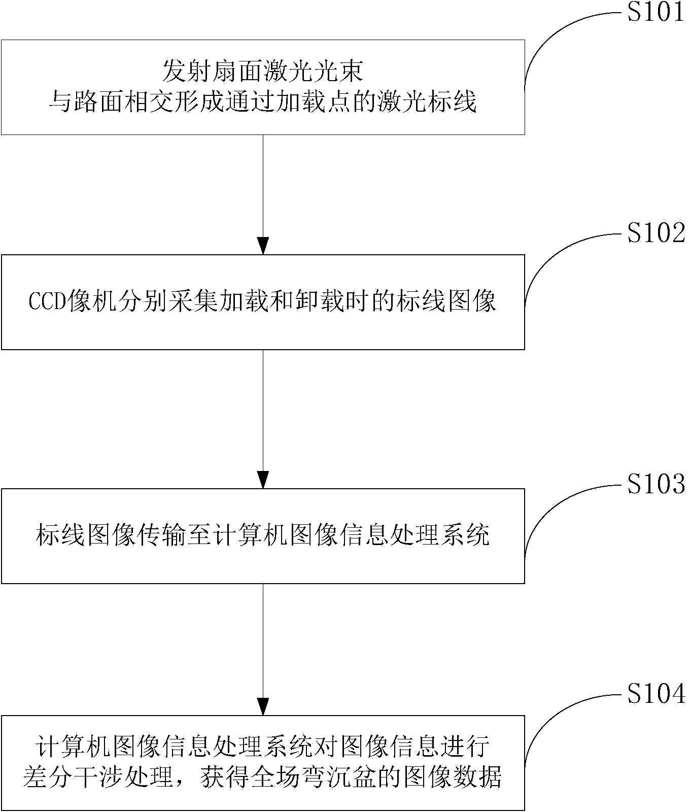
[0040] figure 1 It is an exemplary flowchart of a full-field laser detection method for road surface deflection according to an embodiment of the present invention, wherein a full-field laser detection method for road surface deflection starts at step S101 and ends after step S104.

[0041] In step S101, a sectoral laser beam is emitted to the road surface to be tested to form a laser marking line passing through the loading point of the road surface to be tested.

[0042] The loading point is located at the center of the rear axle of the standard load vehicle, and the standard load vehicle refers to a load vehicle loaded with a standard mass of 10T.

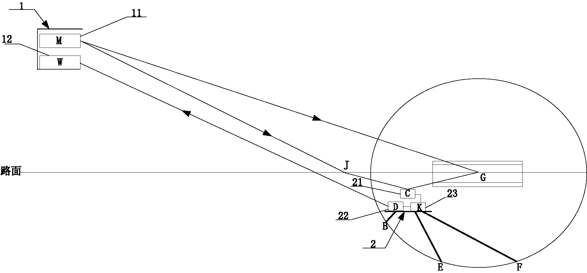
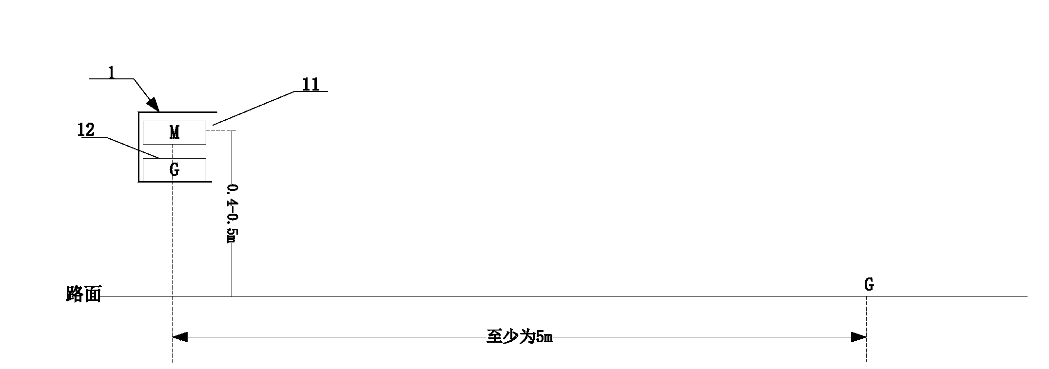
[0043] As a preferred embodiment, in order to prevent the change of the measurement reference from affecting the measurement result, the fan laser ...


PUM


Abstract

The invention provides a pavement deflection full-field laser detection method and system. The method comprises the following steps: emitting a sector laser beam to a pavement to be measured, and forming a laser marking line which passes through a loading point of the pavement to be measured; providing an image acquisition control signal for a charge coupled device (CCD) image acquisition device, and controlling the image acquisition device to acquire a laser marking line image, wherein the operation comprises two-time image acquisition; acquiring two laser marking line images under two conditions that a standard load is loaded on the loading point and the standard load is unloaded from the loading point; transmitting the laser marking line image acquired by the CCD image acquisition device to a computer image information processing system in a wired or wireless mode; and performing image information differential interference processing through the computer image information processing system, thus acquiring image data of a deflection basin. According to the detection system and method provided by the invention, the pavement deflection is detected in a non-contact full-field mode, the distance between a supporting point and a measuring point is large enough, and a measuring basis is reasonably selected.

Description

technical field [0001] The invention relates to the field of surface micro-deformation display and precise measurement, in particular to a full-field laser detection method and detection system for road surface deflection, which is suitable for full-field large-span non-contact intelligent detection of various road subgrade deflection values. Background technique [0002] 1. Technical performance requirements for pavement deflection detection [0003] Pavement deflection is a parameter that characterizes the bearing capacity of the pavement. It is determined by the structure and material of the pavement. Under the action of the standard load wheel, the total vertical deformation value of the roadbed or road surface in the wheel gap is the total deflection (difference between no-load and standard load deformation); or the vertical rebound deformation value is called rebound deflection (standard full load The difference from the deformation after complete unloading), with 0.0...

Claims


Application Information

Patent Timeline
Patent Type & Authority Applications(China)
IPC IPC(8): E01C23/01
Inventor 贺安之贺宁贺斌
Owner TECH TRANSFER CENT CO LTD NANJING UNIV OF SCI & TECH
Why Eureka
Try Eureka