Slag cooler for calcinator

A roasting furnace and slag cooler technology, applied in the field of slag residual heat utilization, can solve the problems of no slag waste heat utilization equipment and immature slag, and achieve high reliability, convenient installation and operation, and good stability

Inactive Publication Date: 2014-03-19
JINING HOWARD ENVIRONMENTAL
View PDF6 Cites 4 Cited by
  • Summary
  • Abstract
  • Description
  • Claims
  • Application Information

AI Technical Summary

Problems solved by technology

However, the slag waste heat utilization technology in the prior art is still immature, especially there is no feasible slag waste heat utilization equipment to choose from

Method used


Image

  • Slag cooler for calcinator
  • Slag cooler for calcinator

Examples


Embodiment Construction

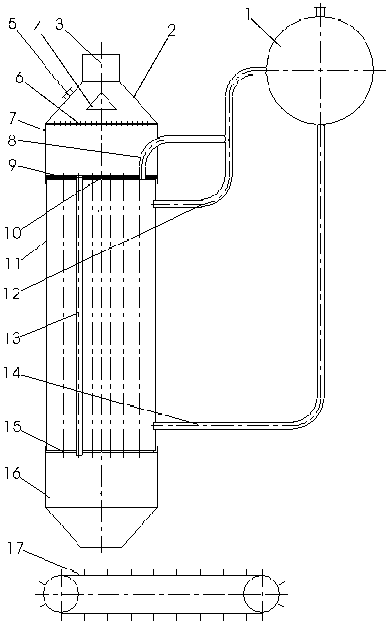
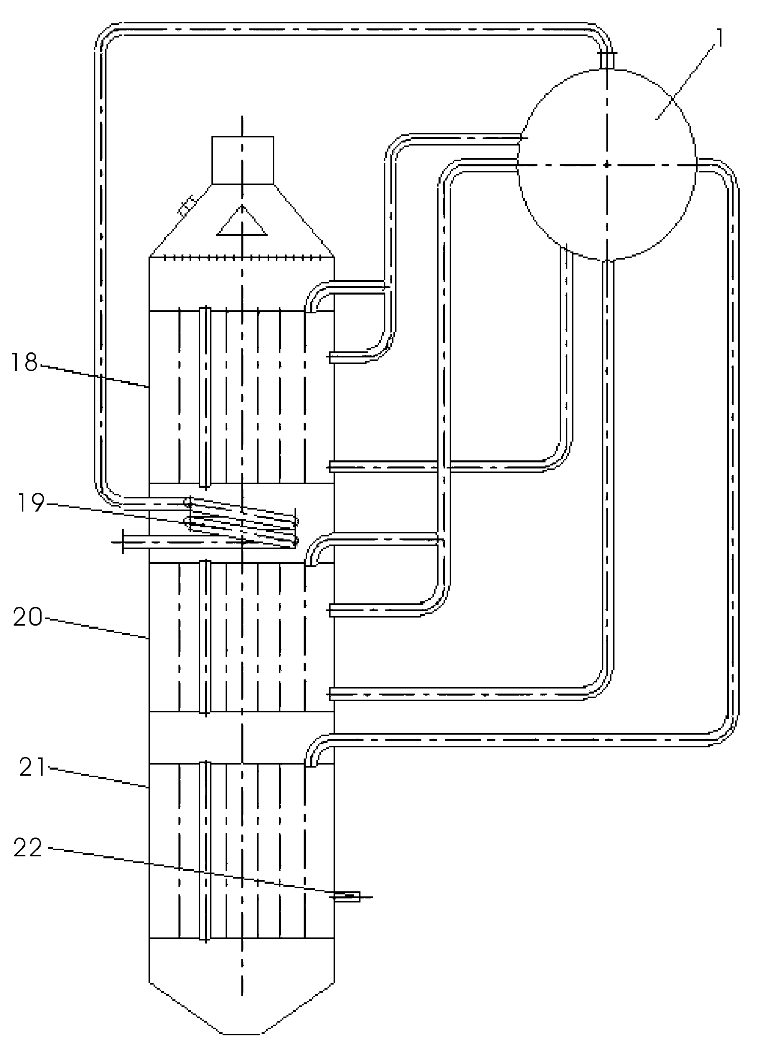
[0008] Now refer to the attached figure 1 And attached figure 2 , described as follows in conjunction with the embodiment: A kind of slag cooler for roasting furnace according to the present invention includes a steam drum 1, an upper end cover 2, a slag inlet 3, a split flow equalizing device 4, an inspection door 5, a leveling layer Flow equalizing device 6, sealing cover plate 7, upper steam-water connecting pipe 8, refractory material 9, upper tube plate 10, outer cylinder body 11, lower steam-water connecting pipe 12, fire pipe 13, descending pipe 14, lower tube plate 15, outlet Slag port 16, slag remover 17, upper evaporator 18, superheater 19, lower evaporator 20, economizer 21 and water supply pipe seat 22. The outer cylinder 11 is the main body of a slag cooler for roasting furnaces according to the present invention, and has a cylindrical structure as a whole. The basic structural form can also be set in a two-stage or multi-stage form on the basis of a single-sta...


PUM


Abstract

A slag cooler for a calcinator includes a steam dome, an upper end cover, a slag inlet, a flow division and equalization device, an inspection door, a flat-layer flow equalization device, a seal cover plate, an upper steam water connecting pipe, fireproof materials, an upper pipe plate, an outer cylinder body, a lower steam water connecting pipe, a fire pipe, a down pipe, a lower pipe plate, a slag outlet, a slag remover, an upper-stage evaporator, a superheater, a lower-stage evaporator, a coal economizer and a water supply pipe seat, wherein a single-stage evaporator is the basic structural form, and the two-stage evaporators or multi-stage evaporators can also be arranged on the basis of the single-stage evaporator; the upper pipe plate is arranged at the upper end of the outer cylinder body in a connected manner, the seal cover plate is arranged above the upper pipe plate in a connected manner, the upper end cover is arranged at the upper end of the seal cover plate in a connected manner, the flat-layer flow equalization device is arranged at the joint of the upper end cover and the seal cover plate, the flow division and equalization device is arranged in the center of the inside of the upper end cover, and the slag inlet is arranged in the center of the upper end of the upper end cover. The slag cooler for the calcinator has the advantages of simple overall structure, and convenience in mounting, operation and use, as well as high stability and reliability.

Description

technical field [0001] The invention relates to a slag residual heat utilization technology, in particular to a slag cooler used in a roasting furnace. Background technique [0002] Currently, slag from industrial fluidized roasters is usually used for metal recovery because it contains many metal elements. However, many units have not utilized the waste heat of slag. For example: most of the slag discharged from the domestic sulfuric acid industry is treated with the method of spraying water outside the rotary cylinder to cool it. This not only loses the waste heat of slag, but also loses water and electricity additionally. Although some units have utilized waste heat from slag, they still produce hot water, and the utilization rate of the calorific value is low. Moreover, the hot water produced by production units often has no usable place, which is not conducive to the utilization of waste heat. When recovering waste heat of this type of slag, in order to facilitate me...

Claims


Application Information

Patent Timeline
Patent Type & Authority Applications(China)
IPC IPC(8): F27D17/00F22B1/04
CPCY02P10/25
Inventor 李继强杨群峰陈瑞广曹颖刘德明
Owner JINING HOWARD ENVIRONMENTAL
Why Eureka
Try Eureka