
Double-electric-control scanning laser phased array radar

A phased array radar and scanning laser technology, which is used in the re-radiation of electromagnetic waves, radio wave measurement systems, and the use of re-radiation, etc. problem, to achieve the effect of reducing false alarms and removing interference

Inactive Publication Date: 2014-03-19
HARBIN INST OF TECH
View PDF5 Cites 30 Cited by
  • Summary
  • Abstract
  • Description
  • Claims
  • Application Information

AI Technical Summary

Problems solved by technology

[0004] The purpose of the present invention is to solve the problem that the existing phased array antenna unit is large in size and the side lobes of the transmitted beam are large, causing the received signal to be interfered, and provides a dual electronically controlled scanning laser phased array radar

Method used


Image

  • Double-electric-control scanning laser phased array radar

Examples


specific Embodiment approach 1

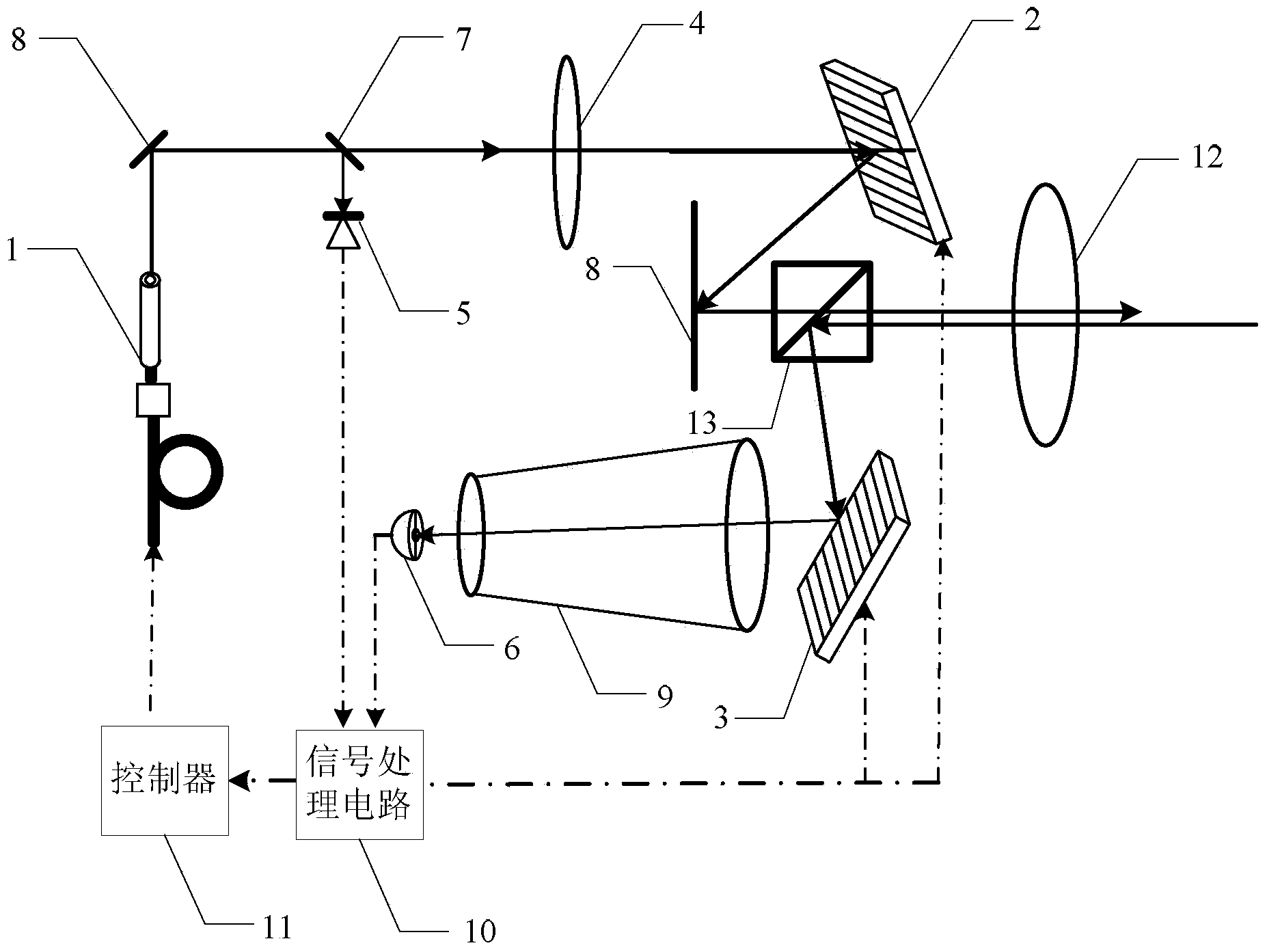
[0013] Specific implementation mode one: the following combination figure 1 Describe this embodiment mode, the dual electronically controlled scanning laser phased array radar described in this embodiment mode, it comprises pulse laser 1, two-dimensional liquid crystal phase modulator 2, two-dimensional micromirror array 3, polarizer 4, detector PIN5, detection Device APD6, beam splitter 7, two mirrors 8, telescope 9, signal processing circuit 10, controller 11, transmitting and receiving optical element 12 and beam splitter 13,

[0014] The pulsed laser light emitted by the pulse laser 1 enters the first reflector 8, is reflected by the first reflector 8, and then enters the beam splitter 7, and the reflected light reflected by the beam splitter 7 enters the detector PIN5, passes through the beam splitter 7 The transmitted light of the polarizer 4 is incident to the polarizer 4, the light transmitted through the polarizer 4 is incident to the two-dimensional liquid crystal ph...

specific Embodiment approach 2

[0021] Embodiment 2: In this embodiment, Embodiment 1 is further described, and the controller 11 is realized by a computer.

specific Embodiment approach 3

[0022] Embodiment 3: This embodiment will further describe Embodiment 1. The process of the controller 11 outputting the control signal to the two-dimensional liquid crystal phase modulator 2 to control the phase distribution of the area where the beam is located is: using the birefringence effect of the liquid crystal to control After the beam passes through each phase control unit, a phase delay occurs, thereby changing the shape and propagation direction of the output beam.


PUM


Abstract

A double-electric-control scanning laser phased array radar relates to laser phased array radars and is used for solving the problem of signal receiving interference due to large unit dimension and large amount of sidelobe of emitted laser beams of existing phase array antennas. According to the double-electric-control scanning laser phased array radar, pulse laser emitted by a pulse laser device is emitted to an optical splitter through a reflector, reflected light is emitted into a detector PIN, transmission light is emitted into a polarizer and then to a two-dimensional liquid crystal phase modulator, the reflected light is emitted into a beam splitter through the reflector, transmission light is emitted to a transmitting / receiving optical element to be emitted off, echo signals are transmitted to the beam splitter through the transmitting / receiving optical element, reflected light is emitted to a two-dimensional micromirror array and then to a telescope, transmission light is emitted to a detector APD (avalanche photodiode), the detector PIN and the detector APD convert light signals into electric signals for outputting to a signal processing circuit, and a controller controls the two-dimension liquid crystal phase regulator, the two-dimensional micromirror array and the pulse laser device. The double-electric-control scanning laser phased array radar is applicable to laser radars tracking multiple high-speed motion targets.

Description

technical field [0001] The invention relates to a laser phased array radar. Background technique [0002] The phased array laser radar has the ability of beam pointing and beam shape to change rapidly, it is easy to form multiple beams, and each beam can be randomly controlled to realize any form of spatial scanning. These characteristics enable the laser radar of the phased array system to perform multiple functions and have the ability to stably track multiple high-speed moving targets, providing technical potential for improving the observation of various low-detectable targets including stealth targets by laser radar. At the same time, compared with optical-mechanical scanning laser radar, optical phased array laser radar has a greater improvement in system volume, weight, and power consumption. [0003] The size of the existing phased array antenna unit is large, and there are many side lobes of the transmitted beam, resulting in low efficiency of the transmitting ante...

Claims


Application Information

Patent Timeline
IPC IPC(8): G01S7/481G01S7/495
CPCG01S7/481G01S7/495G01S17/66
Inventor 靳辰飞张思琦赵远乔天元宋子童翟建华
Owner HARBIN INST OF TECH
Learn More