Light trapping structure for thin film solar cell and manufacturing method thereof

A technology for a solar cell and a light trapping structure, which is applied in the field of solar cells, can solve the problems of limited light trapping effect and complicated processing of the light trapping structure, and achieves the effects of simple structure, wide application range and strong light trapping ability.

Inactive Publication Date: 2014-03-19
INST OF OPTICS & ELECTRONICS - CHINESE ACAD OF SCI
View PDF4 Cites 9 Cited by
  • Summary
  • Abstract
  • Description
  • Claims
  • Application Information

AI Technical Summary

Problems solved by technology

[0004] The technical problem to be solved by the present invention is to propose a thin-film solar cell light-trapping structure based on a microlens array and its manufacturing method in view of the shortcomings of existing thin-film solar cell light-trapping structures such as complex processing and limited light-trapping effect

Method used


Image

  • Light trapping structure for thin film solar cell and manufacturing method thereof
  • Light trapping structure for thin film solar cell and manufacturing method thereof
  • Light trapping structure for thin film solar cell and manufacturing method thereof

Examples


Embodiment 2

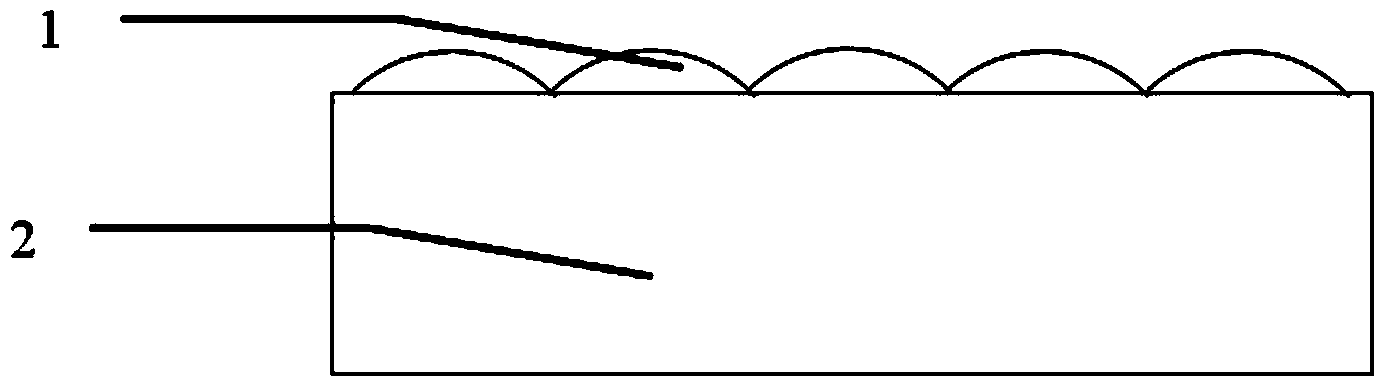
[0043] Embodiment 2 of the present invention is a light-trapping structure with a microlens diameter of 400 μm, a focal length of 2 mm in the base material, and a lens center spacing of 600 μm. The material of the microlens is plastic, and the base thickness is 2 mm.

[0044] The processing steps of the light trapping structure are:

[0045] (1) Make a microlens array on a plastic substrate with a thickness of 2 mm by hot pressing. The diameter of the microlens array is 400 μm, the focal length in the plastic substrate is 2 mm, and the lens center spacing is 600 μm;

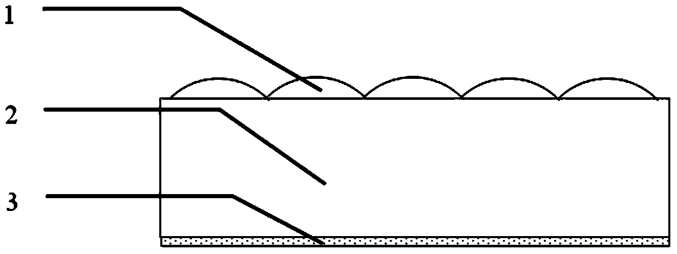
[0046] (2) Coating a layer of negative photoresist with a thickness of 1um on the lower surface of the microlens substrate and pre-baking;

[0047] (3) Use a 365nm ultraviolet exposure machine to irradiate the upper surface of the microlens array to expose the negative photoresist at the focus of the microlens;

[0048] (4) After the exposed negative photoresist is developed, a dot matrix photoresist pattern cor...


PUM


Abstract

The invention provides a light trapping structure for a thin film solar cell and a manufacturing method thereof. The light trapping structure is formed by a micro lens array (1), a micro lens array substrate (2), a reflecting film layer (4) with microhole arrays and a reflection lens (5). The positions of the microhole arrays of are in one to one correspondence with the positions of the focuses of the micro lens array (1) and are coincide with the positions of the focuses of the micro lens array (1). A cavity (6) is formed between the reflecting film layer (4) with the microhole arrays and the reflection lens (5). Sunlight is focused through the micro lens array and then is cast into the cavity through the micro lens array, multiple times of reflection are formed between the reflecting film layer with the microhole arrays and the reflection lens, and thus the light trapping of the sunlight is realized. A thin film solar cell is placed in the cavity, thus the absorption enhancement of the sunlight can be realized, and the photoelectric conversion efficiency is raised. The light trapping structure has the advantages of simple structure, high light energy utilization rate and good compatibility, and the light trapping structure can be widely used in various types of thin film solar cells and has a broad application prospect in the research aspect of the thin film solar cell.

Description

technical field [0001] The invention belongs to the technical field of solar cells, and relates to a light-trapping structure for thin-film solar cells and a manufacturing method. Background technique [0002] In recent decades, with the advancement of science and technology and the development of the economy, the demand for energy in various countries is increasing, and non-renewable energy sources such as electricity, coal, and oil are frequently running out. More and more countries are beginning to look for new clean energy and Renewable resources, including solar energy, wind energy, water energy, geothermal energy, ocean energy, etc. Solar energy will become one of the most promising clean energy for large-scale application in the 21st century due to its advantages of huge reserves, safety, and cleanliness. [0003] At present, the most mature and widely used technology is still crystalline silicon solar cells. However, in order to ensure high photoelectric conversion...

Claims


Application Information

Patent Timeline
Patent Type & Authority Applications(China)
IPC IPC(8): H01L31/054H01L31/18
CPCY02E10/542Y02E10/52Y02P70/50
Inventor 方亮张铁军杨欢邱传凯
Owner INST OF OPTICS & ELECTRONICS - CHINESE ACAD OF SCI
Why Eureka
Try Eureka