
Driving circuit and driving method for improving scanning accuracy of YIG (yttrium iron garnet) filter

A technology of driving circuit and driving method, which is applied in the direction of continuous tuning components, etc., and can solve the problems of low scanning accuracy and slow speed of YIG tuning filter

Active Publication Date: 2014-03-19
CHINA ELECTRONIS TECH INSTR CO LTD
View PDF3 Cites 7 Cited by
  • Summary
  • Abstract
  • Description
  • Claims
  • Application Information

AI Technical Summary

Problems solved by technology

[0008] The present invention proposes a driving circuit and a driving method for improving the scanning accuracy of the YIG filter, which solves the problem of low scanning accuracy and slow speed of the YIG tuning filter in the prior art

Method used


Image

  • Driving circuit and driving method for improving scanning accuracy of YIG (yttrium iron garnet) filter
  • Driving circuit and driving method for improving scanning accuracy of YIG (yttrium iron garnet) filter
  • Driving circuit and driving method for improving scanning accuracy of YIG (yttrium iron garnet) filter

Examples


Embodiment 1

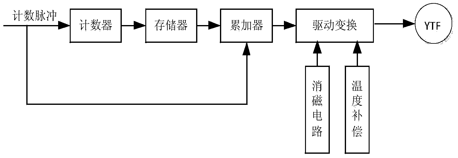
[0037] The schematic diagram of the YIG tuned filter driving circuit realized by the present invention is as figure 2 As shown, it is mainly composed of a counter, a memory, an accumulator, and a drive transformation circuit. The counter is used to count the count pulses, the memory is used to store the calibrated YIG filter driving DAC value under static conditions, and the accumulator is used to start the DAC. value and step DAC value for cyclic accumulation. The drive conversion circuit is composed of DAC, operational amplifier, drive tube and sampling resistor, among which DAC is used to convert the DAC digital value output by the accumulator to analog value, and the operational amplifier is used to realize the proportional adjustment of the drive voltage of the analog value, and the drive tube And the sampling resistor is used to realize the conversion from the driving voltage to the driving current, and the driving conversion circuit has the functions of degaussing, tem...

Embodiment 2

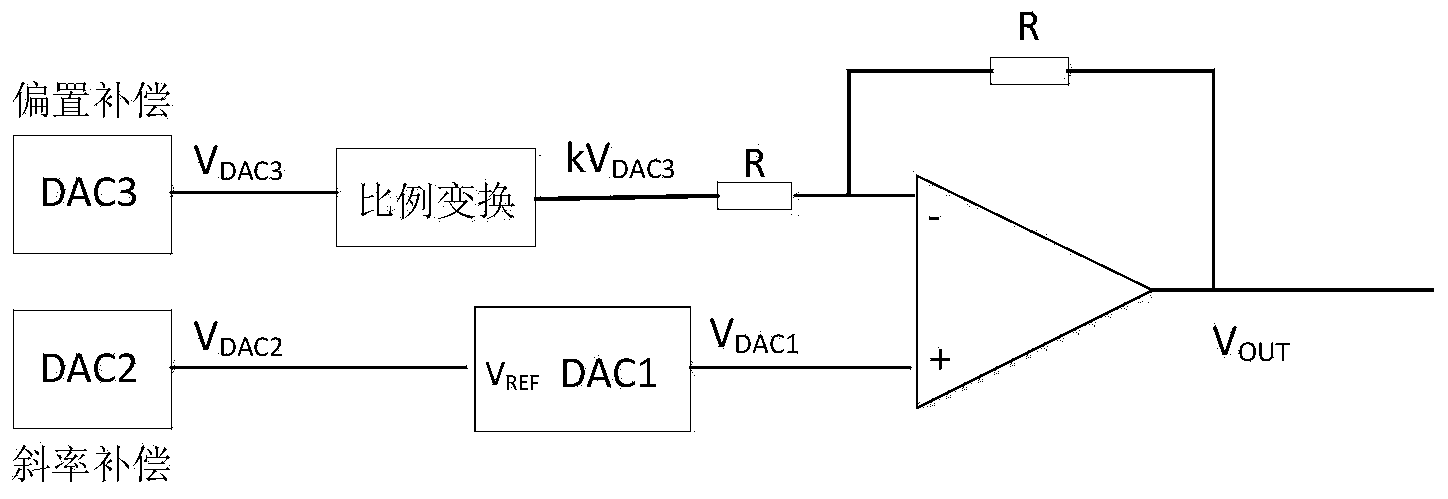
[0055] On the basis of the above examples, if Figure 2-Figure 4 As shown, the present invention is further described a kind of drive circuit that improves the scanning accuracy of YIG filter, wherein, comprise counter, memory, accumulator, drive conversion circuit;

[0056] The counter is used to count the counting pulses, and the counting value of the counter is increased once for each counting pulse;

[0057] The memory is used to store the calibrated YIG filter driving DAC value under static conditions;

[0058] The accumulator is used for cyclically accumulating the initial DAC value and the step DAC value;

[0059] The drive transformation circuit is composed of DAC, operational amplifier, drive tube and sampling resistor, wherein, DAC is used to realize the conversion of the DAC digital value output by the accumulator to the analog voltage value; the operational amplifier is used to realize the ratio of the analog value drive voltage Adjustment; the drive tube and the...


PUM


Abstract

The invention provides a driving circuit and a driving method for improving scanning accuracy of a YIG (yttrium iron garnet) filter. According to the method, a nonlinear tuning curve of a whole scanning frequency band is simulated in a segmentation fitting mode, the whole scanning frequency band is divided into a plurality of small bands, a tuning curve is linear in each small band, and the gradient and the intercept of the tuning curve can be dynamically compensated and corrected in real time according to scanning widths and scanning speeds, so that the scanning accuracy of the YIG filter is improved. By the aid of the scheme, the tuning curve of the YIG tuned filter at different frequencies, different scanning widths and different scanning speeds can be obtained, the scanning process includes calling and real-time dynamic compensation and correction of corresponding DAC (digital-to-analog converter) values under synchronization of count pulse, various software algorithms for eliminating the hysteresis effect of the YIG filter are omitted, so that time is effectively shortened, and the scanning accuracy is improved.

Description

technical field [0001] The invention belongs to the technical field of YIG filter driving, and in particular relates to a driving circuit and a driving method for improving the scanning accuracy of a YIG filter. Background technique [0002] YIG tuned filter is a broadband tuned bandpass filter with wide tuning frequency range, high out-of-band rejection, small size, etc. It is widely used in microwave millimeter wave spectrum analyzer or receiver to preselect signals to eliminate image and Multiple responses. The YIG tuned filter uses the monotone mapping relationship between the self-resonance frequency of the YIG ball and the magnetic field strength in its space to realize the tuning filter. The current drives the YIG tuned filter coil to generate a magnetic field, thereby controlling the synchronous change of the resonance frequency of the YIG ball. YIG tuning filter is a magnetic device, and there is a certain tuning nonlinearity. Even if the driving voltage in the ent...

Claims


Application Information

Patent Timeline
IPC IPC(8): H03J3/16
Inventor 张宁李龙白亮张继彬张冰焦志超付存文
Owner CHINA ELECTRONIS TECH INSTR CO LTD
Learn More