Vacuum deposition device

An evaporation and vacuum technology, which is applied in the field of vacuum evaporation equipment, can solve the problems of inability to correctly control the evaporation speed, uneven evaporation of the evaporation body, and inability to form an evaporation film.

Inactive Publication Date: 2014-03-19
PANASONIC CORP
View PDF8 Cites 3 Cited by
  • Summary
  • Abstract
  • Description
  • Claims
  • Application Information

AI Technical Summary

Problems solved by technology

[0011] However, when a perforated plate gate is provided on the flow path of the vapor deposition material as in the vapor deposition device described in the above-mentioned Patent Document 2, the vapor deposition material may adhere to the perforated plate gate and cause clogging.
When the gate of the perforated plate is clogged, the vapor deposition object may be unevenly deposited, and the vapor deposition rate may not be controlled correctly, so that the vapor deposition film with the desired film thickness may not be formed.

Method used


Image

  • Vacuum deposition device
  • Vacuum deposition device
  • Vacuum deposition device

Examples


Embodiment Construction

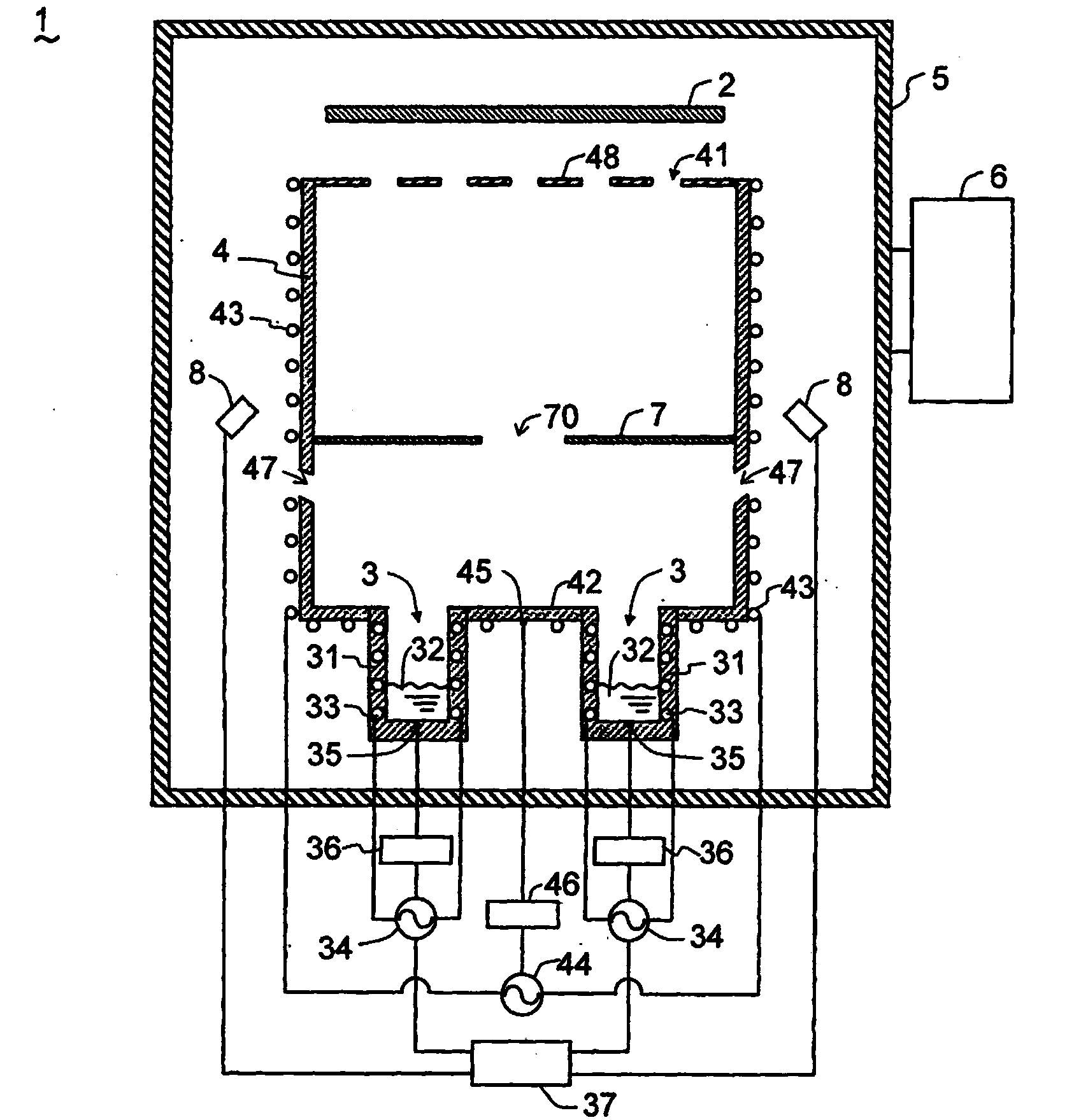
[0038] For the vacuum evaporation device of the first embodiment of the present invention, refer to Figure 1 to Figure 3 Be explained. like figure 1 As shown, the vacuum evaporation device 1 of the present embodiment is provided with a plurality of evaporation sources 3 for evaporating various materials on the evaporation target 2 , and a plurality of evaporation sources 3 and the evaporation target 2 are connected to each other. A cylindrical body 4 surrounded by a space and having an open surface on the vapor-deposited body 2 side. Furthermore, a vacuum chamber 5 is provided which makes the space in which the vapor deposition object 2, the evaporation source 3, and the cylindrical body 4 are arranged to be in a vacuum state. The vacuum chamber 5 is configured to be decompressed into a vacuum state by exhausting the vacuum pump 6 .

[0039] The cylindrical body 4 has an opening surface 41 at one end, and a correction plate 48 for flow rate control described later is provi...


PUM


Abstract

[Problem] To configure a vacuum deposition device so that non-uniformity of a deposited film formed on a body is less likely to occur when multiple evaporation sources are used, and a deposited film with a desired film thickness can be formed. [Solution] The vacuum deposition device (1) is provided with: multiple evaporation sources (3); and a cylindrical body (4) that surrounds the space between the evaporation sources (3) and a body (2) onto which a film is to be deposited, and has an aperture plane (41) on the side facing the body (2) onto which a film is to be deposited. Also, the vacuum deposition device has a partitioning plate (7) that is provided inside the cylindrical body (4). The partitioning plate (7) has aperture sections (70). One or more aperture sections (70) are provided within the range of a circumference having a diameter of D around the center of gravity (P).; The diameter (D) is 2/3 of the maximum value of the distance between two points on the outer circumference of the partitioning plate (7). This configuration can achieve a uniform flux distribution for an evaporation material from the aperture sections (70) of the partitioning plate (7) to the body (2) onto which a film is to be deposited. Thus, non-uniformity of the deposited film formed on the body (2) is less likely to occur when multiple evaporation sources (3) are used, and a deposited film with a desired film thickness can be formed.

Description

technical field [0001] The present invention relates to a vacuum vapor deposition apparatus for forming a thin film by vapor-depositing a vapor deposition material on a vapor deposition object such as a substrate. Background technique [0002] The vacuum evaporation device arranges an evaporation source containing an evaporation material and an evaporation target such as a substrate in a vacuum chamber, and in a state where the vacuum chamber is depressurized, the evaporation source is heated to vaporize the evaporation source, and the vaporization The evaporation material accumulates on the surface of the object to be evaporated to form a thin film. However, a part of the vapor deposition material vaporized from the evaporation source may not travel to the vapor deposition body or adhere to the surface of the vapor deposition body. Such an increase in the vapor deposition material not adhering to the vapor deposition target will cause a decrease in material use efficiency ...

Claims


Application Information

Patent Timeline
Patent Type & Authority Applications(China)
IPC IPC(8): C23C14/24
CPCC23C14/24
Inventor 宫川展幸西森泰辅安食高志北村一树
Owner PANASONIC CORP
Why Eureka
Try Eureka