Roll-cutting tool

A hob cutting and tool technology, applied in metal processing and other directions, can solve the problems of self-expansion and poor cutting quality of the hob cutter, and achieve the effects of simple structure, good general performance and long service life

Active Publication Date: 2014-03-26
宁波新安东密封保温系统有限公司
View PDF9 Cites 11 Cited by
  • Summary
  • Abstract
  • Description
  • Claims
  • Application Information

AI Technical Summary

Problems solved by technology

[0003] The invention solves the problem that the general rolling cutting device in the prior art does not effectively control the independent expansion and contraction of the rolling cutter and the poor cutting quality. The combined innovation of the mechanism and its connection stru

Method used


Image

  • Roll-cutting tool
  • Roll-cutting tool
  • Roll-cutting tool

Examples


Embodiment 1

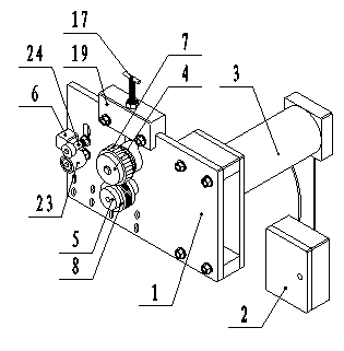
[0029] Example 1: Combining Attachment figure 1 and 2 , a rolling cutting tool, including a frame 1, a control box 2 and a rolling cutting motor 3, a rolling cutting shaft 4, a pressure shaft 5, a die 6 and a spacing adjustment mechanism installed on the frame 1, and the die 6 is fixed on the On one side of the frame 1, the rolling-cutting motor 3 is fixed on the other side of the frame 1, the rolling-cutting motor 3 is connected with the rolling-cutting shaft 4, the wiring of the rolling-cutting motor 3 is connected with the control box 2, and one end of the rolling-cutting shaft 4 is evenly A set of disc-shaped hobbing cutters 7 are provided, and the back of the hobbing cutter 7 is provided with a control mechanism for controlling the expansion and contraction of the hobbing cutter 7. The pressure-receiving wheel 8 matched with the cutter 7, and the spacing adjustment mechanism is linked with the rolling and cutting shaft 4.

[0030] When installing, firstly install the h...

Embodiment 2

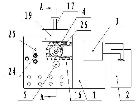
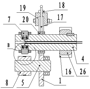
[0031] Example 2: Combining Attachment figure 1 , 2 , 3, 4, 6, a rolling cutting tool, including a frame 1, a control box 2, a rolling cutting motor 3, a rolling cutting shaft 4, a pressure shaft 5, a mold 6, and a spacing adjustment mechanism installed on the frame 1 , the positioning wheel 23 and the positioning bolt 24, the mold 6 is threadedly connected to one side of the frame 1, the hobbing motor 3 is fixed on the other side of the frame 1, and one end of the hobbing shaft 4 is provided with a transmission gear 26, The motor 3 is connected with the transmission gear 26 through the chain 16, the wiring of the hobbing motor 3 is connected with the control box 2, the other end of the hobbing and cutting shaft 4 is evenly provided with a group of disc-shaped hobbing cutters 7, and the back of the hobbing cutter 7 is provided with The control mechanism that controls the expansion and contraction of the hob cutter 7, the control mechanism is composed of a compression spring ...

Embodiment 3

[0033] Embodiment 3, in conjunction with the attached Figure 5 , 6 , 7, 8, 9, a rolling cutting tool, including a frame 1, a control box 2, a rolling cutting motor 3, a rolling cutting shaft 4, a pressure shaft 5, a mold 6, and a spacing adjustment mechanism installed on the frame 1 , the positioning wheel 23 and the positioning bolt 24, the mold 6 is threadedly connected to one side of the frame 1, the hobbing motor 3 is fixed on the other side of the frame 1, and one end of the hobbing shaft 4 is provided with a transmission gear 26, The motor 3 is connected with the transmission gear 26 through the chain 16, the wiring of the hobbing motor 3 is connected with the control box 2, the other end of the hobbing shaft 4 is evenly provided with a group of disc-shaped hobbing cutters 7, and the back of the hobbing cutter 7 is provided with a control The telescopic control mechanism of the hob cutter 7 includes a tension spring 11, an eccentric camshaft 12 and a control motor ...


PUM


Abstract

The invention discloses a roll-cutting tool comprising a machine frame, a control cabinet, a roll-cutting motor, a roll-cutting shaft, a stressed shaft, a templet and an interval adjusting mechanism, wherein the roll-cutting motor, the roll-cutting shaft, the stressed shaft, the templet and the interval adjusting mechanism are installed on the machine frame. The roll-cutting tool is characterized in that the templet is fixed to one side of the machine frame, the roll-cutting motor is fixed to the other side of the machine frame and connected with the roll-cutting shaft, a connecting wire of the roll-cutting motor is connected with the control cabinet, a set of dish-shaped roll-cutting cutters are evenly arranged at one end of the roll-cutting shaft, the back of each roll-cutting cutter is provided with a control mechanism controlling the roll-cutting cutter to stretch or retract, the stressed shaft is arranged under the roll-cutting shaft and provided with stressed wheels which are in fit with the roll-cutting cutters, and the interval adjusting mechanism is in linkage with the roll-cutting shaft. The innovation that the machine frame, the control cabinet, the roll-cutting motor, the roll-cutting shaft, the stressed shaft, the templet, the interval adjusting mechanism and a connection mechanism are combined is achieved, and the roll-cutting tool has the advantages that the universality is good, the roll-cutting cutters are controlled to stretch and retract automatically, the surface of a sealing rubber strip cannot be scratched, and the product quality is good.

Description

technical field [0001] The invention relates to the technical field of mechanical manufacturing, and more specifically relates to a rolling cutting tool for realizing equidistant incisions of sealing rubber strips. Background technique [0002] In the door and window industry, the sealing strip plays the role of waterproof, windproof, shock absorption and noise prevention. The sealing strip is generally installed between the frame and the frame, between the frame and the door and window profiles. Since the doors and windows have four corners, the sealing strip will wrinkle at the corners, which not only has the problem of difficult installation, but also has the problem of poor sealing performance. The general solution is as follows: First, cut the rubber strip into a V shape and then bond it with a specific sealing strip glue. The bonding method cannot guarantee the sealing performance of the sealing strip; , but the corner mold has the problem of high cost. The ideal me...

Claims


Application Information

Patent Timeline
IPC IPC(8): B26D1/22B26D7/26B26D5/16
Inventor 林兆卫杜瑞宁李娜
Owner 宁波新安东密封保温系统有限公司
Why Eureka
Try Eureka