Boiling type biomass gasification process

A biomass and boiling technology, applied in the direction of granular/powder fuel gasification, etc., can solve the problems of burn-through, prone to burn-out, high gas tar content, achieve suitable airflow speed, smooth slag discharge, and prevent tar precipitation Effect

Inactive Publication Date: 2014-03-26
GUANGZHOU XINGUANGHE ENVIRONMENTAL PROTECTION TECH
View PDF8 Cites 4 Cited by
  • Summary
  • Abstract
  • Description
  • Claims
  • Application Information

AI Technical Summary

Problems solved by technology

[0007] Among the above technical solutions, the main problem of the fluidized bed gasification process is the high content of gas ash, and the ash discharge function of the gasif

Method used


Image

  • Boiling type biomass gasification process
  • Boiling type biomass gasification process

Examples


Embodiment 1

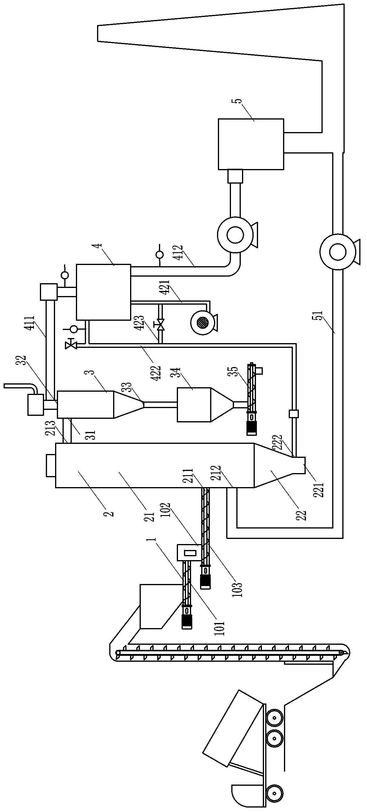
[0049] The boiling type biomass gasification process of the present embodiment comprises the following steps:

[0050] (1) Furnace start-up in the form of a fixed bed: ignite in the gasifier, feed the gasification medium (air) at a small flow rate from the side of the tail ash section of the gasifier, and The feed port on the side is fed into the biomass raw material, and the feed port is located at a position 1 / 4 of the height from the bottom of the reaction section; among them, multi-stage feeding is carried out through a multi-stage feeding device;

[0051] (2) First, the biomass raw material in the gasifier is combusted on the grate; after the biomass raw material generates gas in the state of layer combustion, the gasification medium is increased to make the biomass raw material in the gasifier The gasification reaction is carried out in a boiling state to generate gas; the height of the material accumulated in the reaction section is controlled to be less than 25% of the...

Embodiment 2

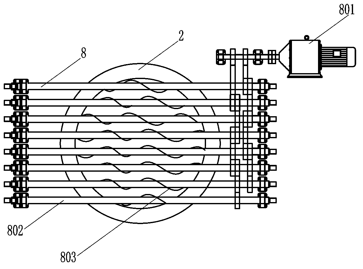
[0063] The difference between this embodiment and Embodiment 1 is that the ash is discharged through the rotating blade type water-cooled grate. Each grate rod can be rotated under the drive of the motor, and each grate rod of the water-cooled grate is equipped with a blade that can be rotated by the grate rod as the rotation axis, so as to discharge slag through the rotation of the blade.

[0064] Such as figure 2As shown, the grate for realizing the process of this embodiment is a water-cooled grate 8, which includes an adjustable-speed driving motor 801 and a plurality of grate bars 802 arranged in parallel. The driving motor 801 is used to drive each grate bar 802 to rotate. Each grate rod 802 is a metal tube with a cavity, and the two ends of each grate rod 802 are located outside the furnace body 2 of the gasifier, and the two ends of each grate rod 802 are equipped with water cooling Rotary joint. Each grate rod 802 is equipped with a helical blade 803, which can be...


PUM


Abstract

The invention provides a boiling type biomass gasification process. According to the boiling type biomass gasification process, reaction is carried out in a gasification furnace, and the gasification furnace comprises a reaction section and a tail ash section; the reaction section and the tail ash section are arranged with one being above the other, and a furnace grate is arranged between the reaction section and the tail ash section; and the boiling type biomass gasification process comprises the following steps: (1) feeding biomass raw material into a feeding opening formed in the side part of the reaction section of the gasification furnace, wherein the feeding opening is positioned below the middle part of the reaction section and arranged in the position having a distance being 1/4-1/2 of the height away from the bottom of the reaction section, and the height of the material accumulated in the reaction section is below 30% of the height of the reaction section; and introducing a gasification medium from the side part of the tail ash section of the gasification furnace; and (2) firstly grate firing the biomass raw material in the gasification furnace on the furnace grate; and then increasing the introduction speed of the gasification medium so that the biomass raw material in the gasification furnace has gasification reaction in a boiling state to generate fuel gas.

Description

technical field [0001] The invention relates to a boiling biomass gasification process. Background technique [0002] At present, the biomass gasification process mainly has two directions, one is the fluidized bed gasification process, and the other is the fixed bed gasification process. The fluidized bed gasification process is the gasification process of biomass fuel in a fluidized state in the furnace; its main characteristic is that the stock of biomass raw materials in the furnace is required to be small, which is convenient for fluidization. The fixed bed gasification process is that the biomass exists in a piled state in the furnace, and the gasification process is completed by layer combustion; its characteristic is that it requires a large stock of biomass raw materials in the furnace. [0003] For example, Chinese patent 01108139.2 discloses a biomass internal circulation conical fluidized bed gasification process, which pulverizes biomass (such as wood chips, br...

Claims


Application Information

Patent Timeline
IPC IPC(8): C10J3/54
Inventor 赵广健
Owner GUANGZHOU XINGUANGHE ENVIRONMENTAL PROTECTION TECH
Why Eureka
Try Eureka