Three-layer series micro-perforated pipe muffler

A micro-perforation and muffler technology, which is applied in the direction of mufflers, machines/engines, engine components, etc., can solve the problems of reduced sound-absorbing materials for mufflers, adverse effects on personnel health, and large volume of mufflers, achieving small back pressure loss and volume reduction The effect of small and wide anechoic frequencies

Active Publication Date: 2014-03-26
WUHAN UNIV OF TECH
View PDF6 Cites 15 Cited by
  • Summary
  • Abstract
  • Description
  • Claims
  • Application Information

AI Technical Summary

Problems solved by technology

The former is not suitable for working in a relatively closed environment, because the sound-absorbing material will inevitably float in the studio under the long-term scouring of the exhaust flow, which will adversely affect the health of personnel; the long-term scouring reduces the sound-absorbing material in the muffler , the noise reduction effect is reduced, so its service life is not long
Resistant mufflers need to use complex cavity or resonance cavity design, so that the volume of the muffler is larger and the exhaust back pressure is larger

Method used


Image

  • Three-layer series micro-perforated pipe muffler
  • Three-layer series micro-perforated pipe muffler
  • Three-layer series micro-perforated pipe muffler

Examples


Embodiment 1

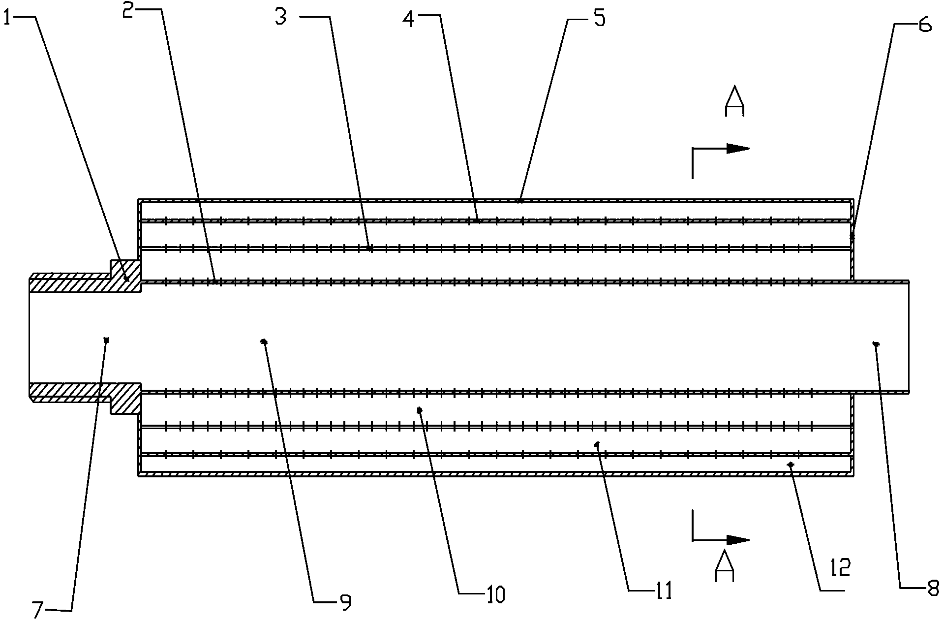
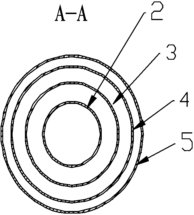
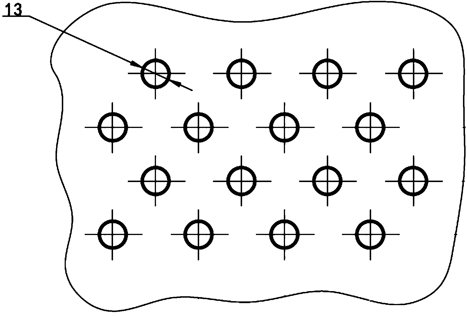
[0023] Such as Figure 1-5 The three-layer micro-perforated tube muffler in series of the present invention includes a metal shell 5, the two ends of the shell 5 are respectively a front end cover 1 and a rear end cover 6, the cross section of the muffler is circular, and the cross section is micro-perforated from the inside to the outside. Hole inner pipe 2, microporous middle pipe 3, microporous outer pipe 4, muffler shell 5.

[0024] The muffler shell 5 is cylindrical; the air intake end and the exhaust end are directly connected through the muffler shell, and the air intake end and the exhaust end are located at the center of the two ends of the cylinder; The three-layer micro-perforated tube divides the inner space of the shell into flow channel I9, cavity II10, cavity III11, and cavity IV12; the three-layer micro-perforated tube is cylindrical, and the micro-porous inner tube 2 is connected The air end 7 and the exhaust end 8 have the same diameter, and are directly con...

Embodiment 2

[0027] with Example 1 figure 1 and Figure 3-5 Basically the same, the difference is that the cross section of the muffler shell 5 is square, the cross section of the microporous outer tube 4 is square, the cross section of the microporous inner tube 3 is square, and the cross section of the microporous inner tube 2 is circular.

[0028] In other embodiments not listed in the present invention, the cross-sectional shape of the muffler shell 5, the microporous outer tube 4, and the microporous inner tube 3 can also be changed to an isosceles polygon, such as a rhombus or a pentagon.

[0029] In the above-mentioned embodiment, when the three-layer micro-perforated tube muffler in series of the present invention is working, the airflow flows in from the air inlet 7 on the front cover 1, flows through the shell 5 and the three-layer series micro-perforated tubes 2, 3, 4, and passes through three The layer of micro-perforated pipe is discharged from the exhaust port 8 on the rear ...


PUM


Abstract

The invention relates to the field of mufflers, and particularly provides a three-layer series micro-perforated pipe muffler which comprises a muffler body, an intake end and an exhaust end. The muffler body is of a three-layer micro-perforated pipe structure for muffling, aperture ranges from 0.1mm to 0.5mm, porosity is less than 5%, gaps are formed between three-layer micro-perforated pipes without being filled with filling materials, the three-layer micro-perforated pipes are different in aperture, equal in porosity and different in cavity volume, and noise in different frequency bands is eliminated. When the muffler is at work, airflow directly flows through a pipeline, and back pressure loss is low. The exhaust muffler is simple in structure, convenient to process and low in cost, and is resistant to high temperature, corrosion and airflow impact and long in service life as being of a pure-metal structure. The muffler has good muffling effect in the whole spectral range and particularly in high-frequency band, and muffling volume reaches 15-25dB.

Description

technical field [0001] The invention relates to the field of mufflers, and specifically provides a muffler with three-layer series micro-perforated tubes used in exhaust and noise reduction of air suction pumps. Background technique [0002] The noise when the air pump is working is mainly composed of gas flow noise and mechanical component motion noise, and the noise frequency range is wide. While eliminating the high frequency part of the gas flow noise, the middle and low frequency part of the mechanical noise cannot be ignored. The traditional resistive muffler needs to be filled with sound-absorbing materials to achieve the purpose of noise reduction; the resistive muffler achieves the purpose of noise reduction through complex structure to generate impedance mismatch. The former is not suitable for working in a relatively closed environment, because the sound-absorbing material will inevitably float in the studio under the long-term scouring of the exhaust flow, which...

Claims


Application Information

Patent Timeline
Patent Type & Authority Applications(China)
IPC IPC(8): F01N1/08
Inventor 刘志恩杜松泽田小青肖生浩郭晶晶颜伏伍彭辅明
Owner WUHAN UNIV OF TECH
Why Eureka
Try Eureka