
Load-sensitive electric proportional multi-loop valve

A load-sensing, multi-way valve technology, applied in the direction of servo meter circuit, lifting device, fluid pressure actuating device, etc., can solve the problems of large commutation impact, low cost, poor control performance, etc., and achieve improved control accuracy and reduced The effect of streamlining pipeline connections and reducing leakage points

Active Publication Date: 2014-03-26
HANGCHA GRP
View PDF9 Cites 24 Cited by
  • Summary
  • Abstract
  • Description
  • Claims
  • Application Information

AI Technical Summary

Problems solved by technology

[0003] At present, 5-10 ton forklifts at home and abroad require a large flow rate when lifting, and require a small flow rate when tilting or other attachments. However, 5-10 ton forklifts are commonly used to manually operate the multi-way reversing valve with two gears. The quantitative system of the pump, when the two pumps are converging when operating, when tilting or other attachments are operating, because the required oil is very small, the excess oil source provided by the quantitative pump is often unloaded at the pressure set by the safety valve, which causes the engine to work at idle speed. If the torque is too small, it is easy to stop the flame, and the energy waste is huge. Moreover, this kind of manual multi-way reversing valve has a large operating force, a large reversing impact, and poor control performance, but it has a simple structure and low cost.
However, with the advancement of science and technology and the higher and higher requirements of people, manual valves can no longer meet people's requirements; in addition, when the actuator has precise micro-movement requirements, the above-mentioned solution is difficult to achieve

Method used


Image

  • Load-sensitive electric proportional multi-loop valve

Examples


Embodiment Construction

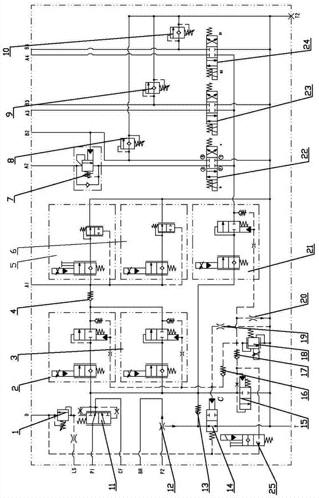
[0013] like figure 1 As shown, this embodiment includes a dynamic load sensing pressure compensation valve 11, a safety valve I1 and a pressure compensation flow regulating valve I12; wherein the oil inlet of the dynamic load sensing pressure compensation valve 11 is connected to the gear pump P1, and an oil outlet is connected to the steering gear The other oil outlet is connected to the main oil circuit of the multi-way valve, and the LS signal oil port of the compensation valve is connected with the steering gear LS port and the oil inlet of safety valve I1 at the same time, and the oil outlet of safety valve I1 is connected with the oil return port D is connected; on the one hand, the main oil road is connected with a lifting circuit and a hydraulic one-way valve I4 in sequence, and the outlet of the hydraulic one-way valve I is respectively connected with the lifting oil port A1 and the descending circuit connected with the oil outlet and the oil return port T On the one ...


PUM


Abstract

The invention relates to a load-sensitive electric proportional multi-loop valve. The load-sensitive electric proportional multi-loop valve aims to enable all loops to work with different loads, save energy and reduce environmental pollution. According to the technical scheme, the load-sensitive electric proportional multi-loop valve comprises a main oil path, a raising loop, an inclined joint, an attachment joint, a logical direction valve, a two-way solenoid valve, a proportional electric overflow valve and a two-way hydraulic control reversing valve, the main oil path is communicated with two gear pumps P1, P2, the raising loop is connected to the main oil path through an electronic proportional pressure compensation flow control valve, the inclined joint and the attachment joint are connected to the main oil path through an electronic proportional pressure compensation flow control valve, the logical direction valve is connected to the main oil path, the two-way solenoid valve and the proportional electric overflow valve are connected to an oil inlet of the logical direction valve, and the two-way hydraulic control reversing valve is used for controlling whether the gear pump P2 supplies oil to the main oil path or not. The load-sensitive electric proportional multi-loop valve is applied to the technical field of hydraulic system control valves of 5-10t forklifts.

Description

technical field [0001] The invention relates to a multi-way valve, in particular to a load-sensitive electric proportional multi-way valve, which is mainly applicable to the technical field of control valves in hydraulic systems of 5-10 ton forklift trucks. Background technique [0002] The multi-way reversing valve is a combined valve with two or more reversing slide valves as the main body. The product can be widely used in various engineering machinery, agricultural machinery and mining machinery. There are at least two actuators to be controlled by the multi-way reversing valve. Since different actuators require different working flows, and the oil source is configured according to the maximum flow, when only one actuator acts or the actuator speed is low , the excess oil can only be unloaded under high pressure, resulting in loss of function and a large amount of heat, which is extremely unfavorable to the life of the system and components. In recent years, people hav...

Claims


Application Information

Patent Timeline
IPC IPC(8): F15B13/06
CPCF15B11/17B66F9/22F15B2211/20576F15B2211/30575F15B2211/351F15B2211/353F15B2211/4053F15B2211/40569F15B2211/40592F15B2211/50536Y10T137/2529
Inventor 刘真李元松陈锡泼赵晓伟孙大海曹讯
Owner HANGCHA GRP
Learn More