Non-smooth surface fluid friction resistance testing device and testing method

A non-smooth surface, fluid friction technology, used in fluid dynamics tests, measuring devices, testing of machine/structural components, etc. Research immaturity and other issues to achieve reliable test results, easy operation, and accurate test results

Inactive Publication Date: 2014-03-26
HARBIN ENG UNIV
View PDF5 Cites 18 Cited by
  • Summary
  • Abstract
  • Description
  • Claims
  • Application Information

AI Technical Summary

Problems solved by technology

However, the research on the device for measuring the frictional resistance of fluid to a fixed surface is still immature. There are mainly four principles for measuring the frictional resistance of fluid to a solid surface, namely the strain balance test method, the suspension displacement resistance test method, and the differential pressure flow resistance test method. 1. Rotational viscometer shear stress test method, the principle of the present invention is basically the same as the strain balance test method, but due to the high price of the strain balance, it is necessary to research and design a non-smooth surface fluid with low cost, simple structure and convenient test The frictional resistance test device is particularly important
[0003] At present, the non-smooth surface and surface coating structure fluid friction resistance test devices are mostly focused on the pressure difference flow resistance test method, such as the patent application number: 201110112635.7, named "a method and device for testing the frictional resistance coefficient of pipelines" and The patent publication number is: CN202013316U, the name is "differential pressure type flow resistance tester", which is suitable for the flow resistance test of pipelines, but not for the flow resistance test of non-smooth surface plates

Method used


Image

  • Non-smooth surface fluid friction resistance testing device and testing method

Examples


Embodiment Construction

[0018] The present invention is described in more detail below in conjunction with accompanying drawing example:

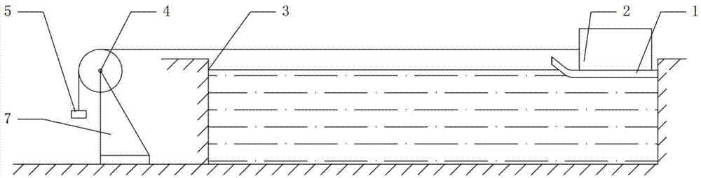
[0019] combine figure 1 , the present invention includes non-smooth surface plate 1, buoyancy material 2, pool 3, fixed pulley 4, weight 5, timer, support 7. The weight 5 bypasses the fixed pulley 4 and the buoyancy material 2 is connected together with a stay wire, the buoyancy material 2 is fixedly connected with the non-smooth surface plate 1, and the fixed pulley 4 is fixed on the support 7.

[0020] Wherein, the front end of the non-smooth surface plate 1 is tilted at a certain angle to reduce or eliminate the pressure difference resistance between the non-smooth surface plate 1 and the buoyancy material 2; Ensure that the pulling force received by the buoyancy material 2 is equal to the gravity of the weight 5; the length of the pool 3 is greater than the height H of the weight 5 from the ground, so as to ensure sufficient timing time and reduce timing erro...


PUM


Abstract

The invention aims to provide a non-smooth surface fluid friction resistance testing device and a testing method. The testing device comprises a pool, a buoyancy material, a support, a fixed pulley, a weight and a pull rope. A flat plate to be tested and the buoyancy material are fixed together, the pool is filled with fluid, and the flat plate to be tested and the buoyancy material jointly float on the fluid. The support is fixed to the position beside the pool, the fixed pulley is installed on the support, the pull rope is wound around the fixed pulley, one end of the pull rope is connected with the buoyancy material, and the other end of the pull rope is connected with the weight. The pull rope keeps horizontal between the fixed pulley and the buoyancy material and is higher than the wall surfaces of the pool, namely the tension exerted on the buoyancy material is equal to the gravity of the weight, the gravity of the weight is larger than the friction resistance of the flat plate, and thus the flat plate can move forward under the effect of gravity of the weight. The testing principle is simple and visualized, the testing device is different from other devices used for estimating a resistance reduction effect of a non-smooth surface, the friction resistance of the non-smooth surface can be directly tested, and the testing result is reliable.

Description

technical field [0001] The invention relates to a test device and a test method, in particular to a test device and a test method for fluid friction resistance. Background technique [0002] At present, relevant scholars at home and abroad have carried out extensive and in-depth theoretical exploration and applied research on the problem of motion drag reduction between fluid and solid interfaces, and have successfully achieved remarkable progress in many aspects. Since the problem of drag reduction can directly affect the energy consumption and mechanical properties of equipment, the research on this problem has always been concerned by experts and scholars from various countries. The research methods are mainly from theoretical analysis, numerical simulation, model test and other aspects. The drag reduction performance of the sample is tested in the test device and the required conclusions are drawn, and then put into practical engineering applications. Whether it is theo...

Claims


Application Information

Patent Timeline
Patent Type & Authority Applications(China)
IPC IPC(8): G01M10/00
Inventor 赵刚李芳刘维新杜军伟臧东阳孙壮志毕红时王晶晶
Owner HARBIN ENG UNIV
Why Eureka
Try Eureka