Visual sample positioning operating system and method based on light spot detection

A sample positioning and operating system technology, applied in optics, measuring devices, optical components, etc., can solve the problems of operator inconvenience, poor adjustability and flexibility, lack of visual operation function of position sensing technology, etc., and achieve a simple optical path structure. , high portability, high flexibility

Active Publication Date: 2014-03-26
TSINGHUA UNIV
View PDF8 Cites 43 Cited by
  • Summary
  • Abstract
  • Description
  • Claims
  • Application Information

AI Technical Summary

Problems solved by technology

As mentioned above, in the instrument using invisible light wave as the detection method, it is necessary to ensure that the focus of the measurement optical path is at the point to be measured on the surface of the sample during measurement; in addition, the existing sample positioning operating system usually uses a contact positioning method to move the sample to a specific measurement point. Position, its adjustability and flexibility are poor, it is difficult to adjust the positioning position conveniently when adjusting the measurement optical path; moreover, the existing position sensing technology lacks visual operation function, which brings inconvenience to the operator, especially the invisible band spectrometer , it is difficult for the operator to monitor the measurement light wave under the existing unmarked positioning means, so it is impossible to judge whether the sample measurement point has been accurately positioned
Therefore, the above factors lead to the low friendliness of the sample positioning operation module in the prior art, and cannot meet the sample automatic operation requirements of precision measuring instruments such as terahertz time-domain spectrometers.

Method used


Image

  • Visual sample positioning operating system and method based on light spot detection
  • Visual sample positioning operating system and method based on light spot detection
  • Visual sample positioning operating system and method based on light spot detection

Examples


Embodiment Construction

[0017] The present invention will be described in detail below in conjunction with the accompanying drawings and embodiments.

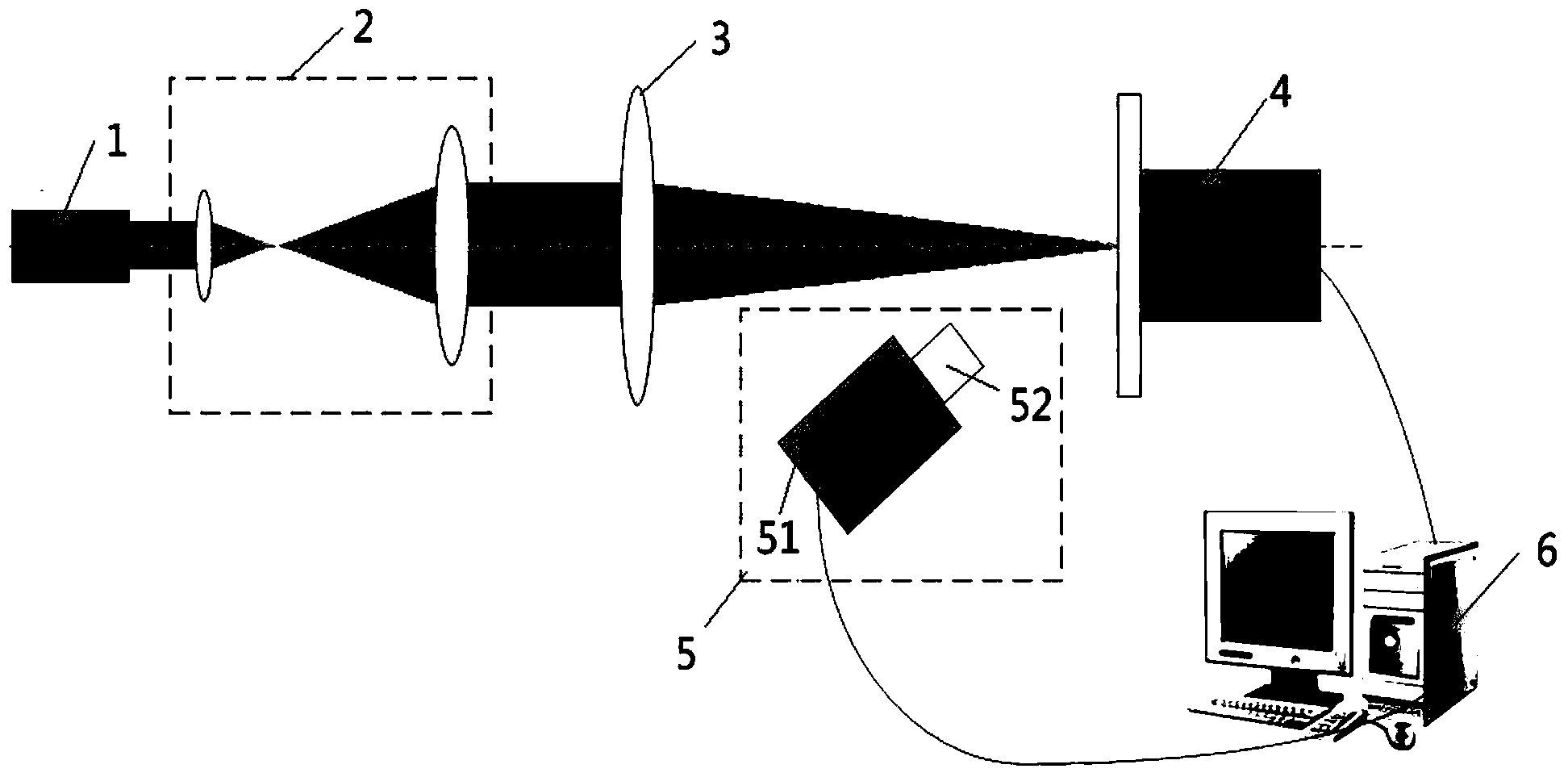
[0018] Such as figure 1 As shown, the visual sample positioning operating system based on spot detection of the present invention includes a visible light laser source 1, a collimating beam expanding unit 2, a beam focusing unit 3, an electronically controlled mobile sample stage 4, and a CCD image acquisition unit 5 and a computer6. The sample to be tested is loaded on the electronically controlled mobile sample stage 4 through an existing sample carrier, and the visible laser light source 1 is used as the marking light source, and the visible laser light emitted by it passes through the collimating beam expanding unit 2 and the beam focusing unit 3 in turn to form a cone. A marked light path; the tapered marked light path is emitted to the sample to be tested to form a marked spot, and the CCD image acquisition unit 5 collects the marked spot and s...


PUM


Abstract

The invention relates to a visual sample positioning operating system and a visual sample positioning operating method based on light spot detection. The system comprises a visible laser source, a collimation beam expansion unit, a light beam condensation unit, an electric control mobile sample table, a CCD (charge coupled device) image acquisition unit and a computer, wherein a sample to be detected is loaded on the electric control mobile sample table; visible laser emitted by the visible laser source sequentially passes through the collimation beam expansion unit and the light beam condensation unit to form a conical marking light path; the marking light path is emitted to the sample to be detected to form a marking light spot; the CCD image acquisition unit acquires the marking light spot and sends the marking light spot to the computer; the computer processes the received marking light spot image to obtain marking light spot parameter information, judges a defocusing state of the marking light spot according to the marking light spot information to search a focusing position and controls the electric control mobile sample table to adjust the position of the sample to be detected according to the searched focusing position, so that automatic focusing of the sample to be detected is realized. The visual sample positioning operating system and the visual sample positioning operating method based on the light spot detection can be widely applied to an automatic sample positioning operation.

Description

technical field [0001] The invention relates to a high-precision sample automatic positioning operating system and method, in particular to a visual sample positioning operating system and method based on spot detection. Background technique [0002] In many precision measuring instruments, especially some non-contact instruments that use invisible light waves as measurement methods, such as terahertz spectrometers, infrared spectrometers, ultraviolet spectrometers, etc., the manual operation of measuring samples or the low degree of automation of the operation module will cause serious problems. It greatly affects the positioning of the sample measurement point, thereby affecting the measurement accuracy and speed. Therefore, the precise positioning of the sample and the automatic operation control system are very critical to improve the performance of the instrument. [0003] The sample positioning operating system generally includes a position sensing module and a servo ...

Claims


Application Information

Patent Timeline
Patent Type & Authority Applications(China)
IPC IPC(8): G01N21/01G02B7/28
Inventor 王崝曹良才金国藩章恩耀
Owner TSINGHUA UNIV
Why Eureka
Try Eureka