Reflecting mirror wavefront coding imaging system

A wavefront encoding and imaging system technology, applied in the field of optics, can solve the problems of optical transfer function reduction, damage consistency, etc., and achieve the effects of size change, reduced installation difficulty, and simplified wavefront encoding optical system

Inactive Publication Date: 2014-03-26
SUZHOU UNIV
View PDF1 Cites 7 Cited by
  • Summary
  • Abstract
  • Description
  • Claims
  • Application Information

AI Technical Summary

Problems solved by technology

[0004] In view of this, the present application provides a reflective mirror wavefront encoding imaging system, which is used to solve the problem that when the existing wavefront encoding technology is applied to the reflection imaging system, additional phase difference will be introduced, which will cause a significant decrease in the optical transfer function and damage the consistency. sexual problems

Method used


Image

  • Reflecting mirror wavefront coding imaging system
  • Reflecting mirror wavefront coding imaging system
  • Reflecting mirror wavefront coding imaging system

Examples


Embodiment Construction

[0023] The technical solutions in the embodiments of the present application will be clearly and completely described below in conjunction with the accompanying drawings in the embodiments of the present application. Obviously, the described embodiments are only some of the embodiments of the present application, not all of them. Based on the embodiments in this application, all other embodiments obtained by persons of ordinary skill in the art without making creative efforts belong to the scope of protection of this application.

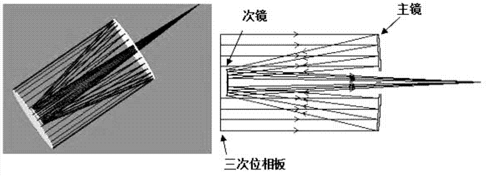
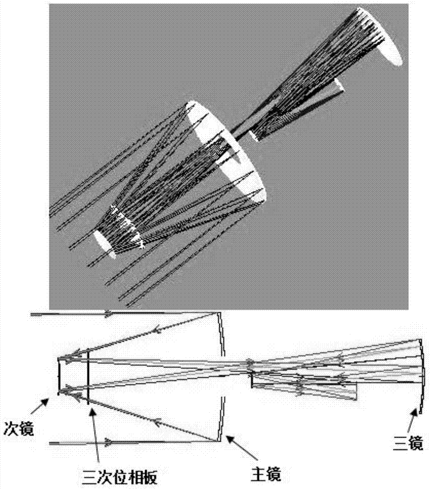
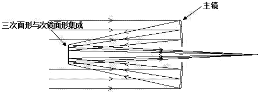
[0024] First of all, let’s introduce Wavefront Coding (WFC for short), which is a technology developed in the 1990s that can expand the focal depth of the system. Dowski and Cathey proposed in 1995 to add a specially designed aspheric phase plate to the aperture or exit pupil of the traditional imaging system to encode the subject, so that the modulation transfer function (MTF) of the system is within a larger focal depth range It is not sensitive t...


PUM


Abstract

The invention discloses a reflecting mirror wavefront coding imaging system, which at least comprises a primary mirror and a secondary mirror, wherein the surface shape of any lens in the primary or secondary mirror integrates a specific phase-coding surface shape. The reflecting mirror wavefront coding imaging system is used for realizing the wavefront coding imaging of an object without an additional phase plate for coding light waves, so that a conventional optical wavefront coding system is greatly simplified, the size and the weight of the whole system are reduced, and difficulty in the alignment of the system is reduced.

Description

technical field [0001] The present application relates to the field of optical technology, and more specifically, to a mirror wavefront encoding imaging system. Background technique [0002] Wavefront Coding (WFC for short) is a technology developed in the 1990s that can expand the focal depth of the system. Dowski and Ccthey proposed in 1995 to add a specially designed aspheric phase plate at the diaphragm or exit pupil of the traditional transmission imaging system to encode the object, so that the modulation traditional function (MTF) of the system can be in a larger focal depth range The interior is not sensitive to defocus, and can form blurred intermediate images with minimal differences in a large depth of field, and then the blurred image is restored to a clear image through a unified digital filter. This technology is applied in the transmissive system. On the basis of the original system, a separate phase plate is added to encode the wavefront, and a good encoding...

Claims


Application Information

Patent Timeline
Patent Type & Authority Applications(China)
IPC IPC(8): G02B27/52G02B27/00
Inventor 王钦华赵效楠许峰韦晓孝
Owner SUZHOU UNIV
Why Eureka
Try Eureka