Ion generation method and ion source
一种离子生成、离子源的技术,应用在离子源领域,能够解决晶片污染等问题
- Summary
- Abstract
- Description
- Claims
- Application Information
AI Technical Summary
Problems solved by technology
Method used
Image
Examples
no. 1 Embodiment approach )
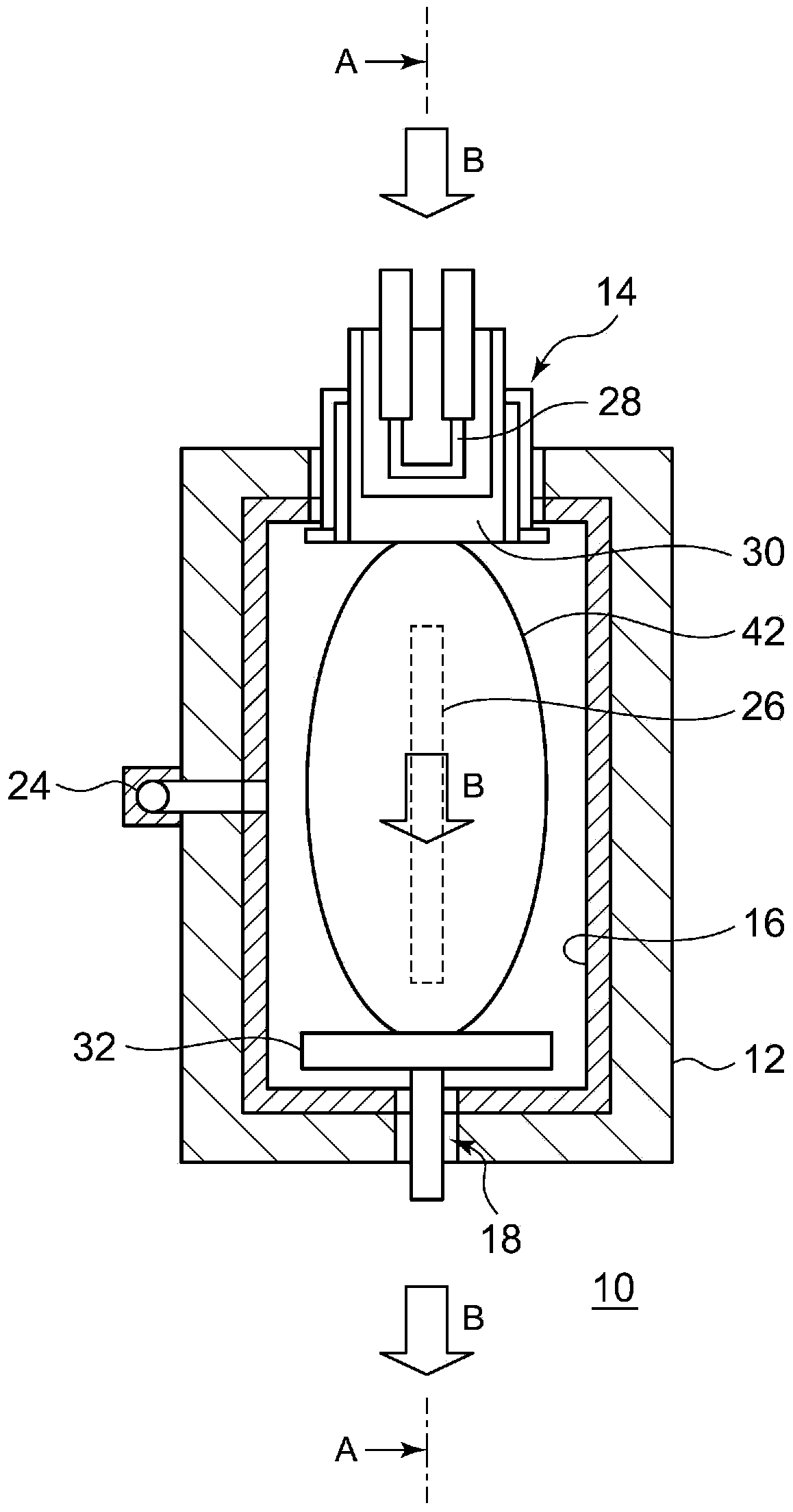
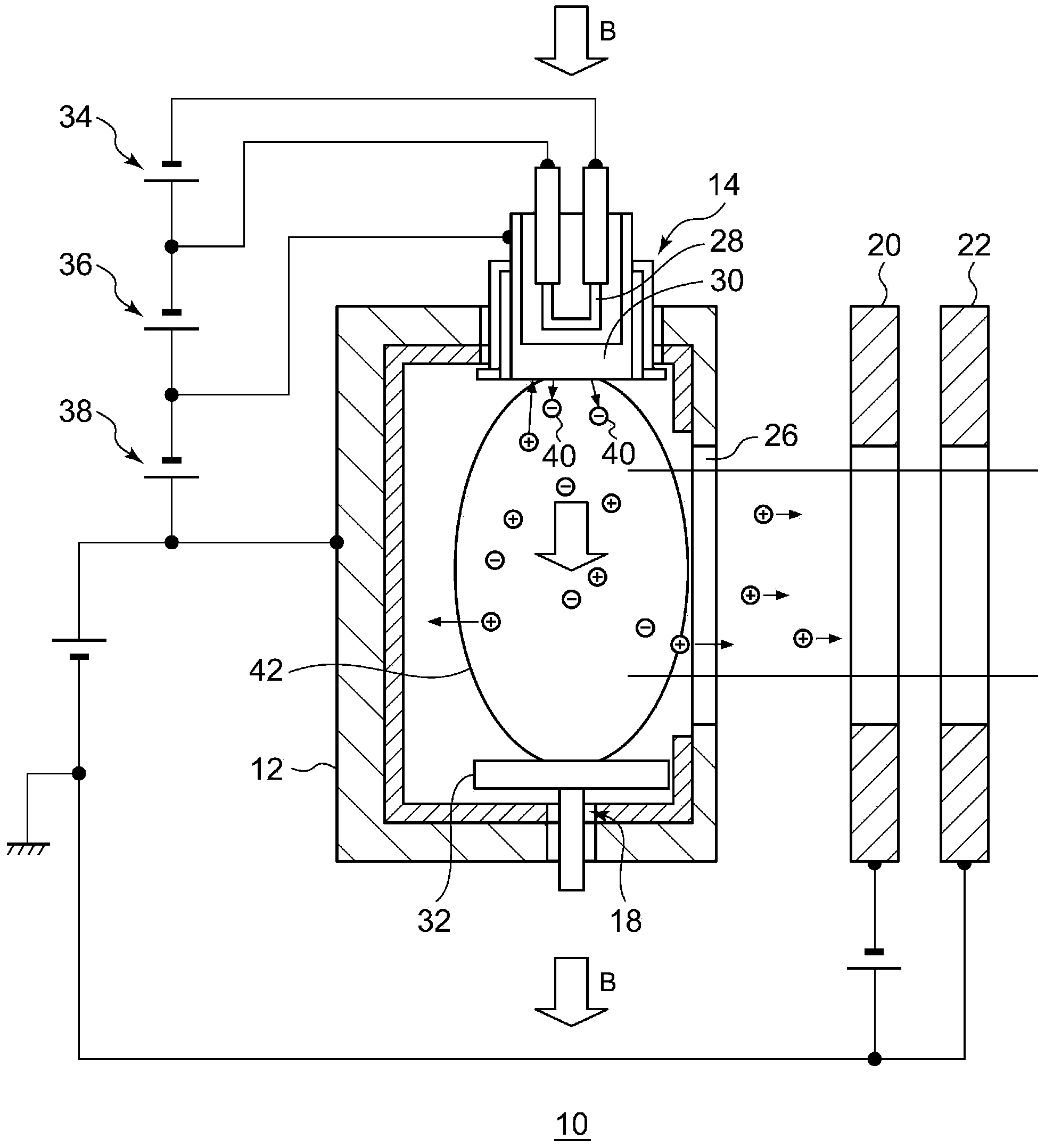
[0024] figure 1 It is a schematic diagram showing the inside of the arc chamber of the ion source according to the first embodiment. figure 2 yes means figure 1 Schematic of the A-A cross-section of the ion source shown.
[0025] The ion source 10 according to the first embodiment is a DC discharge ion source, and includes an arc chamber 12, a thermionic emission part 14, a liner 16, a reflector 18, a suppression electrode 20, a ground electrode 22, and various power sources.
[0026] The arc chamber 12 is formed with a gas inlet 24 for introducing a source gas, and a front slit 26 as an opening for extracting an ion beam.
[0027] The thermal electron emission unit 14 emits thermal electrons into the arc chamber, and has a filament 28 and a cathode 30 . The reflector 18 is provided at a position facing the thermoelectron emitter 14 and has a reflector 32 . The cathode 30 and the reflector 32 are opposed and arranged approximately in parallel. The bushing 16 is provided ...
no. 2 Embodiment approach )
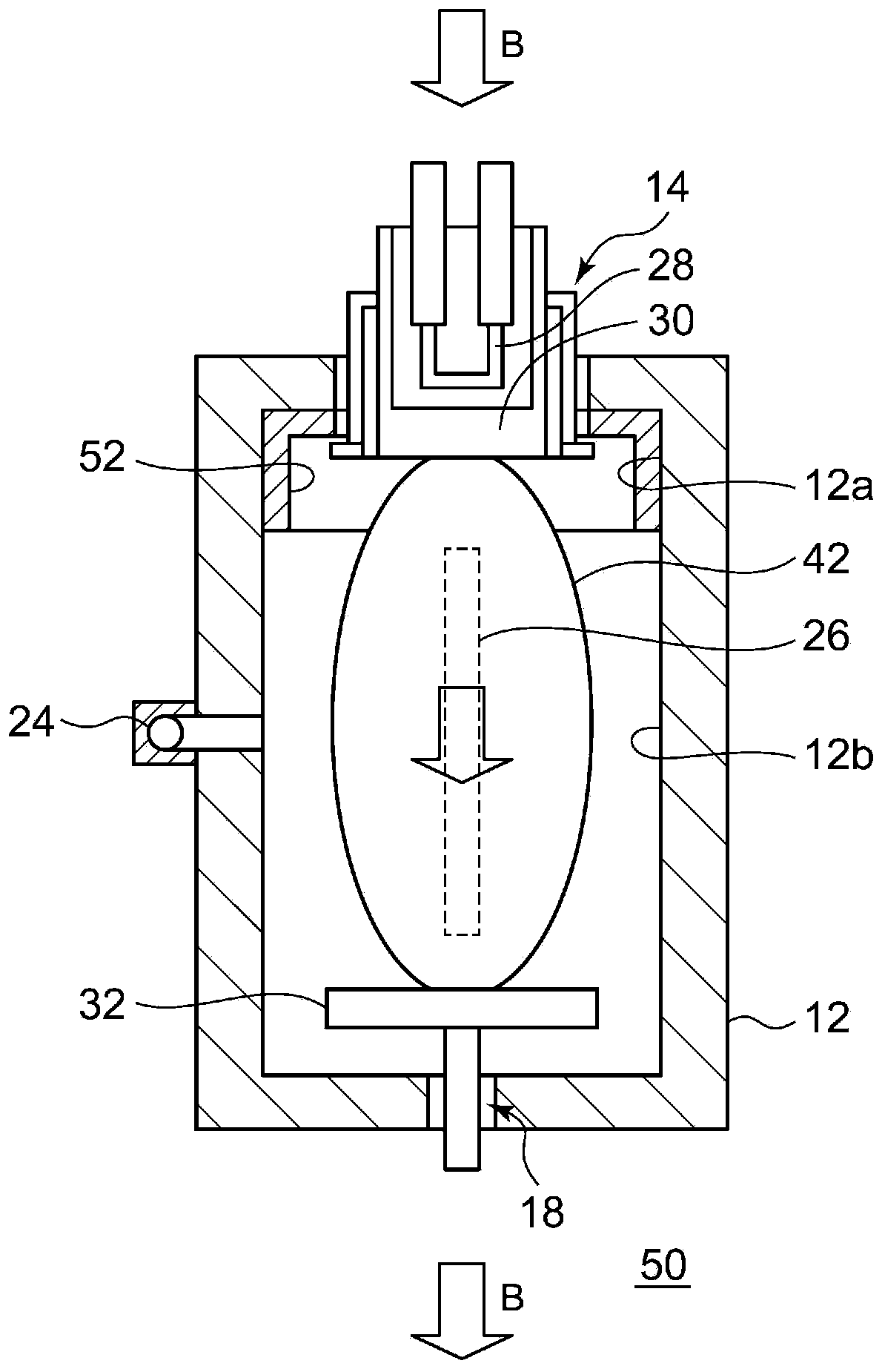
[0053] image 3 It is a schematic diagram showing the inside of the arc chamber of the ion source according to the second embodiment. The ion source 50 according to the second embodiment is different from the ion source 10 according to the first embodiment in the shape of the liner.
[0054] In the ion source 50 , the arc chamber 12 has a liner-covered region 12 a covered by the liner 52 in the vicinity of the thermal electron emission portion 14 , and an exposed area 12 b not covered by the liner 52 . Since radicals are easily generated in the vicinity of the thermal electron emitting portion 14 , by arranging the bushing 52 near the thermal electron emitting portion 14 , the radicals can be effectively removed. On the other hand, by providing the exposed region 12b not covered by the liner, the amount of the liner 52 can be reduced, and excessive generation of ion beams can be suppressed from the material of the liner 52 .
no. 3 Embodiment approach )
[0056] Figure 4 It is a schematic diagram showing the inside of the arc chamber of the ion source according to the third embodiment. The ion source 60 according to the third embodiment is different from the ion source 10 according to the first embodiment in the shape of the liner.
[0057] In the ion source 60 , the arc chamber 12 has a liner-covered region 12 a covered by the liner 62 near the repeller 18 facing the thermionic emission part 14 , and an exposed area 12 b not covered by the liner 62 . Since radicals are easily generated in the vicinity of the reflector 18 , by arranging the bush 62 in the vicinity of the reflector 18 , the radicals can be effectively removed. On the other hand, by providing the exposed region 12 b not covered by the liner 62 , it is possible to reduce the amount of the liner 62 and suppress excessive generation of ion beams from the material of the liner 62 .
PUM
 Abstract
Description
Claims
Application Information
 - R&D
- Intellectual Property
- Life Sciences
- Materials
- Tech Scout
- Unparalleled Data Quality
- Higher Quality Content
- 60% Fewer Hallucinations
Browse by: Latest US Patents, China's latest patents, Technical Efficacy Thesaurus, Application Domain, Technology Topic, Popular Technical Reports.
© 2025 PatSnap. All rights reserved.Legal|Privacy policy|Modern Slavery Act Transparency Statement|Sitemap|About US| Contact US: help@patsnap.com


