Terminal structure for RJ connector, as well as RJ connector module and RJ connector system with same

A terminal structure and connector technology, which is applied to the parts, connections, and contact parts of the connection device, can solve the problems of conductive terminal impedance mismatch, insertion loss, and output signal strength reduction, and achieve reduced insertion loss and good impedance. The effect of matching and improving the efficiency and effect of signal transmission

Active Publication Date: 2014-03-26
DELTA ELECTRONICS INC
View PDF4 Cites 1 Cited by
  • Summary
  • Abstract
  • Description
  • Claims
  • Application Information

AI Technical Summary

Problems solved by technology

[0005] In addition, on the signal transmission path of the transmission system, the problem of impedance mismatch is easily generated between the conductive terminals, which in turn causes insertion loss (insertion loss) during signal transmission. loss), resulting in a decrease in the strength of the output signal

Method used


Image

  • Terminal structure for RJ connector, as well as RJ connector module and RJ connector system with same
  • Terminal structure for RJ connector, as well as RJ connector module and RJ connector system with same
  • Terminal structure for RJ connector, as well as RJ connector module and RJ connector system with same

Examples


Embodiment Construction

[0061] A terminal structure of an RJ connector according to a preferred embodiment of the present invention will be described below with reference to related drawings, wherein the same components will be described with the same reference symbols.

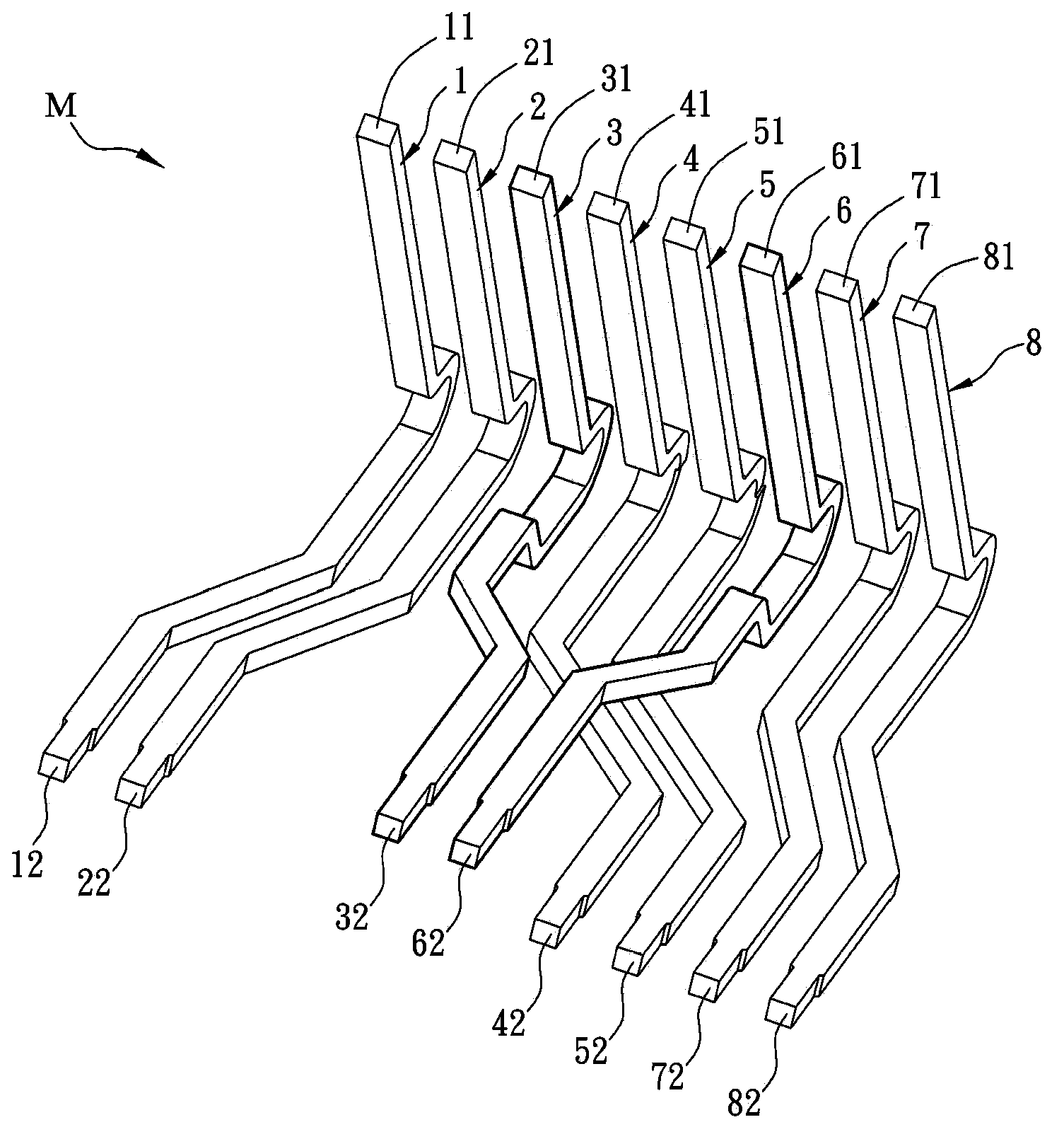
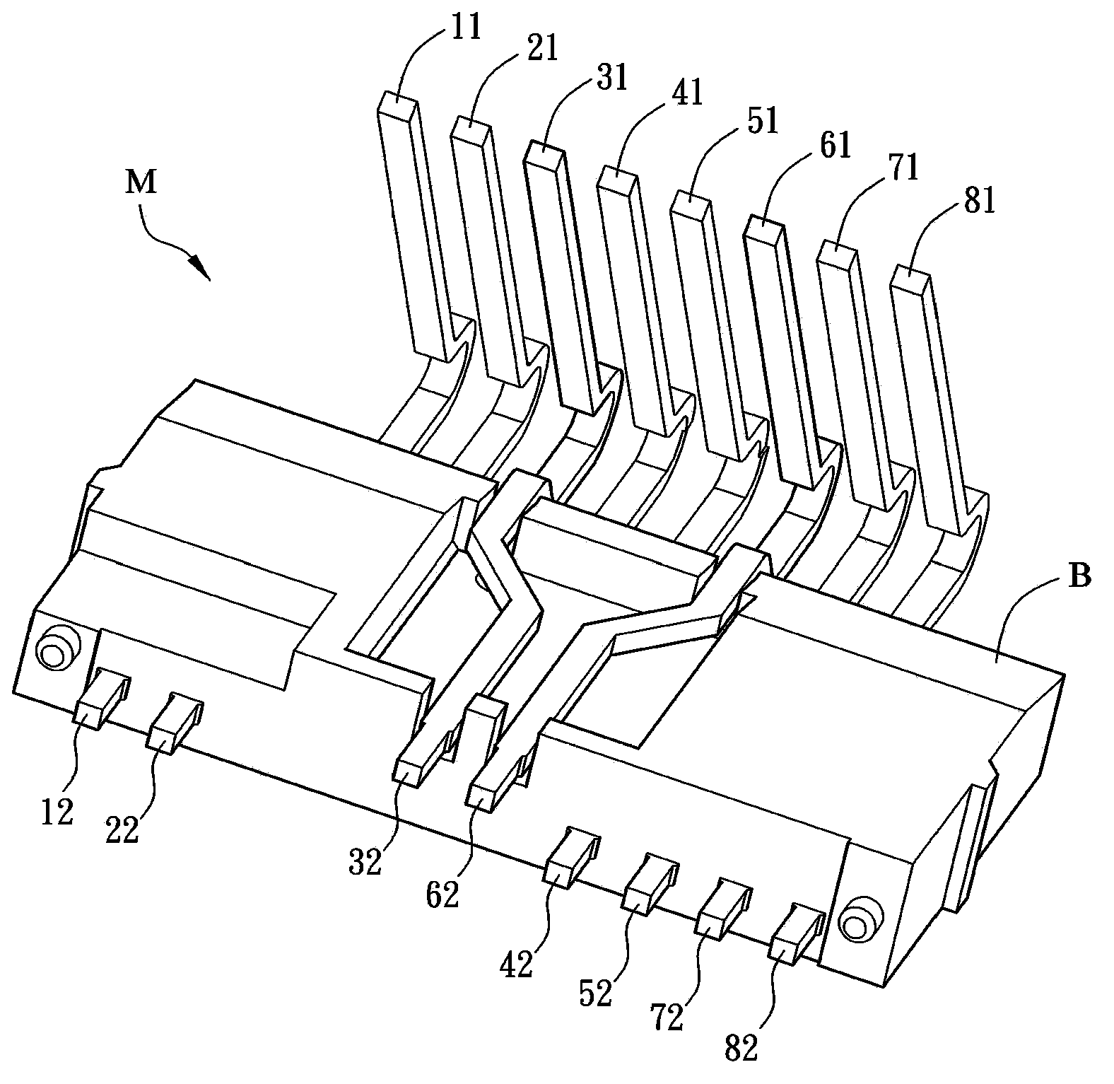
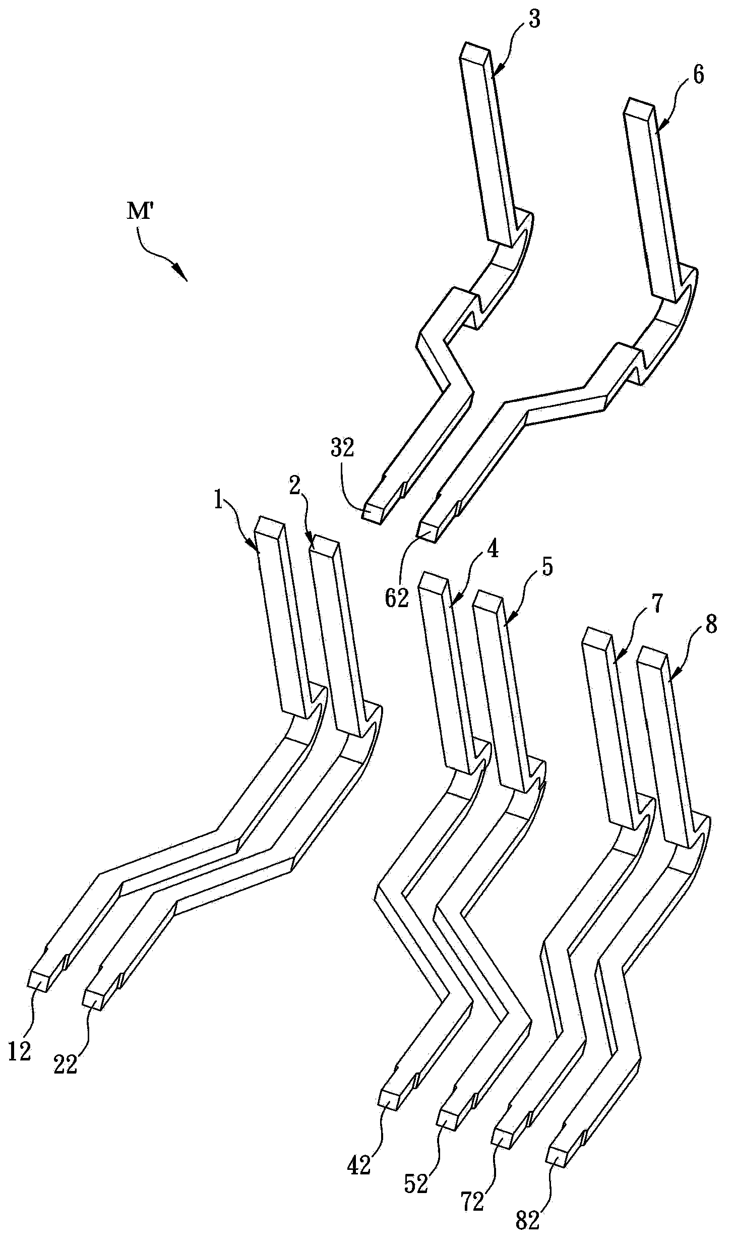
[0062] Figure 1A It is a schematic appearance diagram of a terminal structure of an RJ connector in a preferred embodiment of the present invention, Figure 1B It is a schematic diagram of the appearance of an RJ connector in a preferred embodiment of the present invention. Please also refer to Figure 1A and Figure 1B As shown, the terminal structure M includes a base B and eight terminals, which are respectively the first terminal 1, the second terminal 2, the third terminal 3, the fourth terminal 4, the fifth terminal 5, the sixth terminal 6, the Seventh terminal 7 and eighth terminal 8 . In this embodiment, the terminal structure M of the RJ connector is applied to a Netcom connector, wherein the terminal structure M can b...


PUM


Abstract

The invention provides a terminal structure for an RJ connector. The terminal structure comprises a base and eight terminals. The eight terminals include a first terminal, a second terminal, a third terminal, a fourth terminal, a fifth terminal, a sixth terminal, a seventh terminal and an eighth terminal. One end of each terminal has a contact part respectively. The contact parts are arranged adjacent to each other. The other end of each terminal is bent to form an insertion part, and the insertion parts are inserted into the base. The distance of the insertion parts of the third and the sixth terminals is less than the distance of adjacent contact parts. The invention further provides an RJ connector module and an RJ connector system. With the terminal structure provided in the invention, the crosstalk interference and insertion loss inside a connector can be reduced, so that the signal resolution and accuracy are improved.

Description

[0001] Technical field [0001] The invention relates to an RJ connector, in particular to a terminal structure of the RJ connector. Background technique [0002] With the development of science and technology, most of the electronic devices used in the electronic information industry tend to be micro-sized and multi-functional. In order to facilitate the transmission of data between different electronic devices, several communication protocols with different specifications have also been developed. At the same time, corresponding electrical connectors have also been developed for each communication protocol for electrical connection between different electronic devices for data transmission. . In recent years, the large-scale connectors operating on the network interface are twisted pair connectors, and subdivided twisted pair connectors can be roughly divided into two categories: RJ45 connectors and RJ11 connectors. [0003] In recent years, electronic devices have gradually...

Claims


Application Information

Patent Timeline
Patent Type & Authority Applications(China)
IPC IPC(8): H01R13/02H01R13/6461H01R13/6473
Inventor 戴进忠施华盛
Owner DELTA ELECTRONICS INC
Why Eureka
Try Eureka