Charging system and charging base of electronic equipment

A charging base and charging system technology, applied in battery circuit devices, current collectors, electric vehicles, etc., can solve the problems of low power conversion efficiency, high product cost, affecting battery life, etc., and meet the requirements of high power conversion efficiency and setting location. Low, no impact on battery life

Inactive Publication Date: 2014-03-26
荆涛
View PDF6 Cites 10 Cited by
  • Summary
  • Abstract
  • Description
  • Claims
  • Application Information

AI Technical Summary

Problems solved by technology

[0006] In summary, inductive wireless charging has the following disadvantages: (1) low power conversion efficiency; (2) high heat generation, which affects battery life; (3) slow charging speed; (4) high product cost; (6) Electromagnetic waves may affect human health, etc.
[0007] For one or more problems existing in the above-mentioned inductive wireless charging technology, no effective solution has been proposed yet

Method used


Image

  • Charging system and charging base of electronic equipment
  • Charging system and charging base of electronic equipment
  • Charging system and charging base of electronic equipment

Examples


Embodiment Construction

[0044] It should be noted that, in the case of no conflict, the embodiments in the present application and the features in the embodiments can be combined with each other. The present invention will be described in detail below with reference to the accompanying drawings and examples.

[0045] Firstly, an example of the charging base provided in this specific implementation manner will be introduced.

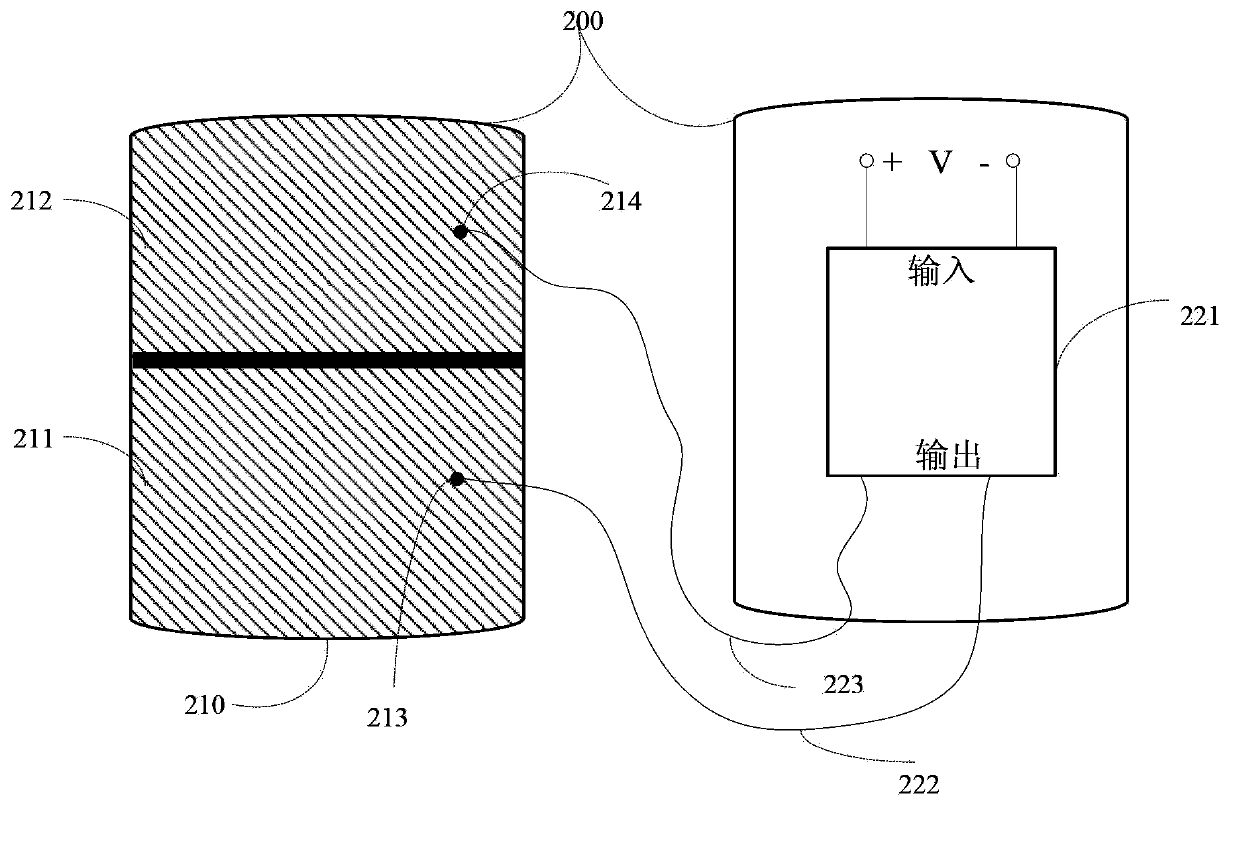
[0046] figure 2 is a schematic diagram of a charging base according to an embodiment of the present invention, such as figure 2 As shown, the charging base 200 includes a power input interface (not shown in the figure), a control unit 221 and an electrode 210 .

[0047]The power input interface is an interface for the charging base to connect to an external power supply device, which can be a USB interface to connect to an external power supply device, or a power adapter interface to directly connect to the mains.

[0048] The input end of the control unit 221 is connected ...


PUM


Abstract

The invention discloses a charging system of electronic equipment and a charging base of the electronic equipment. The charging base comprises the following components of: a power source input interface which is used for connecting an external power source supplying device; a control unit of which the input end is connected with the power source input interface; and an electrode which comprises a first electrode plate and a second electrode plate, wherein the first electrode plate is connected with a first output end of the control unit, and the second electrode plate is connected with a second output end of the control unit. With the charging system and the charging base of the electronic equipment of the invention adopted, charged equipment can directly contact with the charging base, such that power transmission can be realized, and a charging process of the charged equipment can be accomplished, and in the charging process, power conversion efficiency is high, and no heat is emitted, and the service life of a battery will not be affected; with direct charging realized, a charging speed can be very fast; electromagnetic and magnetoelectric conversion devices are not required to be set, and therefore, the product is low in cost and convenient to carry; and at the same time, short-circuiting will not occur between the electrode plates, and charging is safe, and a requirement for a setting position of a charging electrode of the charged equipment is low.

Description

technical field [0001] The invention relates to the field of electronic equipment, in particular to a charging system and a charging base for electronic equipment. Background technique [0002] With the ever-changing functions of smart electronic products, the power consumption of electronic products has increased rapidly. How to enable a variety of powerful smart electronic products (including smart phones, tablet computers, and portable instruments, etc.) to get a more effective power supply while maintaining their flexible and portable features has become the most urgent issue for manufacturers of smart electronic products. solved puzzles. At the same time, due to the slow innovation of battery technology, it is impossible to produce small-volume and large-capacity batteries in a short period of time, so a variety of wireless charger solutions have emerged as the times require. [0003] Currently, wireless chargers for portable devices generally use induction technology...

Claims


Application Information

Patent Timeline
Patent Type & Authority Applications(China)
IPC IPC(8): H02J7/00
Inventor 荆涛
Owner 荆涛
Why Eureka
Try Eureka