Cooling power source control system for exciting power cabinets

A technology of excitation power cabinet and power control, which is applied in emergency power arrangement, cooling/ventilation/heating transformation, electrical components, etc., can solve the problems of unit safety and stability, hidden safety hazards, easy burning, and increased operation risks, etc., so as to eliminate the main and backup Power short-circuit, reduce the risk of downtime, shorten the effect of reconstruction time

Active Publication Date: 2014-03-26
DATANG HUANGDAO POWER GENERATION
View PDF3 Cites 3 Cited by
  • Summary
  • Abstract
  • Description
  • Claims
  • Application Information

AI Technical Summary

Problems solved by technology

[0006] 1. The power circuit of the cooling system of the power cabinet uses a secondary relay contact to connect the primary power circuit, resulting in insufficient contact capacity and easy burning
[0007] The original system adopts the scheme of connecting two relay contacts in parallel to increase the contact capacity. If the contact resistance of the two parallel contacts is inconsistent, there will be uneven distribution of the two contacts during operation, which may cause one of the circuits to exceed the allowable contact. Rated current operation, and then the contacts in the circuit are overheated, burned, and open-circuit faults gradually occur, and then all the current will be transferred to another contact, and the other contact will also be overheated, burned, and open due to overload soon. The switching contacts of the power switching relay are all blown, the cooling power supply of the power cabinet is lost, and the excitation system reports a serious fault and shuts down
[0008] 2. The setting of the monitoring point of the power monitoring circuit of the cooling system of the power cabinet cannot fully reflect the power failure of the cooling system
Because the voltage monitoring relay is connected to the incoming side of the power switching relay, that is, the upper port of the relay, it can only monitor the power supply of the cooling power switching circuit. When the power switching relay fails and the output power is lost, the cooling power monitoring system still judges as If the power supply is normal, it cannot really monitor the cooling power supply. When a fault occurs, the backup power supply cannot be put into operation automatically, which will cause the cooling fan power supply of the power cabinet to lose power and cause shutdown
[0009] 3. The power switching circuit of the cooling system of the power cabinet must be controlled by four input quantities, two output quantities of the main engine of the excitation regulator, and two voltage relays and two two-position relays of the outer circuit. The circuit is complicated and the reliability is poor. Prone to problems
[0010] 4. The two sets of excitation regulators are not completely independent, and there are some common circuits and components. During the operation of the equipment, especially when the defect is eliminated during the operation of the unit, it will pose a great safety hazard to the safety and stability of the unit.
[0011] 5. It is necessary to formulate temporary measures to ensure safety, which increases the workload of maintenance personnel
[0014] (3) Once the temperature of the cooling power switching contact is abnormally changed and the temperature of each contact is inconsistent, it is necessary to manually switch the fan power supply to the backup power supply immediately, which increases the operational risk

Method used


Image

  • Cooling power source control system for exciting power cabinets

Examples


Embodiment Construction

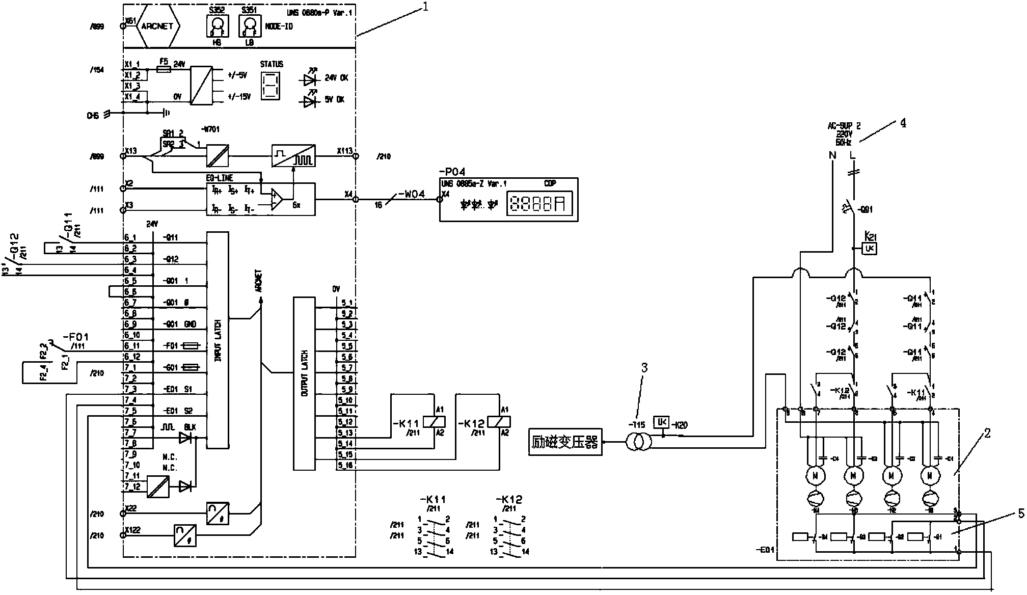
[0032] Below in conjunction with accompanying drawing and embodiment the present invention will be further described:

[0033] Such as figure 1 As shown, the cooling power supply control system of the excitation power cabinet of the present invention includes a plurality of power cabinets 2 and an excitation regulator control cabinet 1, each power cabinet 2 includes: a working power supply 3 for supplying power to the working fan, and is used to supply power to the standby fan The standby power supply 4 is used to monitor the power failure alarm circuit 5 of the working power supply 3 and the standby power supply 4; the working power supply 3 is connected to the working fan after passing through the voltage relay K20, the circuit breaker Q11 and the relay K11, and the standby power supply 4 is connected to the working fan through the voltage relay K21, The circuit breaker Q12 and the relay K12 are connected to the standby fan; the input terminal of the power failure alarm circ...


PUM


Abstract

The invention discloses a cooling power source control system for exciting power cabinets. The cooling power source control system for the exciting power cabinets comprises the power cabinets, an excitation regulator control cabinet and power supplies and the power supplies comprise the working power supply and the emergency power supply; each power cabinet comprises a plurality of working fans, a plurality of standby fans and a power-down alarming circuit; the working power supply is connected with the working fans after being connected with a voltage relay K20, a breaker Q11 and a relay K11 and the standby power supply is connected with the standby fans after being connected with a voltage relay K21, a breaker Q12 and a relay K12; the power-down alarming circuit is connected with the excitation regulator control cabinet. The cooling power source control system for the exciting power cabinets guarantees that when the main power supply breaks down, the power supply of the cooling fan is rapidly switched to the emergency power supply or the working fan is switched to one standby fan for work, frequent switching caused by shaking of the power supplies is avoided, and the hidden danger that due to instability of the power supplies, the working power supply and the emergency power supply compete with each other in the process of frequent switching of the working power supply and the emergency power supply and a short circuit of the working power supply and the emergency power supply is generated is eradicated.

Description

technical field [0001] The invention relates to the field of thermal power generating sets, in particular to a cooling power supply control system for an excitation power cabinet. Background technique [0002] The rectifier bridge cooling system of the excitation system of the existing 670MW supercritical thermal power generation unit was originally a forced cooling method with dual power supply automatic switching and dual redundant fans. The excitation system cooling power supply system provides power. [0003] The excitation system has 5 power cabinets, and each power cabinet is equipped with two cooling fans for main and backup. A total of 10 cooling fans are in operation during normal operation, and there are 10 backup fans. When the unit is running, the total rated current of the cooling fan power supply running in the five power cabinets is 12.7A, and the rated current of the contacts of the power cabinet cooling power switching relay is 10A. Because the capacity of...

Claims


Application Information

Patent Timeline
Patent Type & Authority Applications(China)
IPC IPC(8): H02J9/06H05K7/20
Inventor 邱永刚
Owner DATANG HUANGDAO POWER GENERATION
Why Eureka
Try Eureka