Calibration method and calibration circuit for transmitted power of digital microwave transceiver

A transceiver and transmission power technology, applied in the field of microwave radio frequency, can solve the problems of unstable transmission link gain, difficult production, affecting the accuracy of transmitter output power, etc.

Active Publication Date: 2014-03-26
波达通信设备(广州)有限公司
View PDF3 Cites 31 Cited by
  • Summary
  • Abstract
  • Description
  • Claims
  • Application Information

AI Technical Summary

Problems solved by technology

[0002] The transmitter part of a digital microwave transceiver (radio frequency unit) is generally composed of multiple amplifiers, mixers, filters, and attenuators. Due to the poor consistency of microwave devices, it is greatly affected by temperature, causing the entire transmission link to The gain is unstable, which affects the accuracy of the output power of the transmitter (that is, the actual output power of the transmitter deviates greatly from the preset value); with the development of the communication industry, the operating frequency of digital microwave transceivers is getting higher and higher, and its passband Wider and wider, in such a wide freque

Method used


Image

  • Calibration method and calibration circuit for transmitted power of digital microwave transceiver
  • Calibration method and calibration circuit for transmitted power of digital microwave transceiver
  • Calibration method and calibration circuit for transmitted power of digital microwave transceiver

Examples


Embodiment

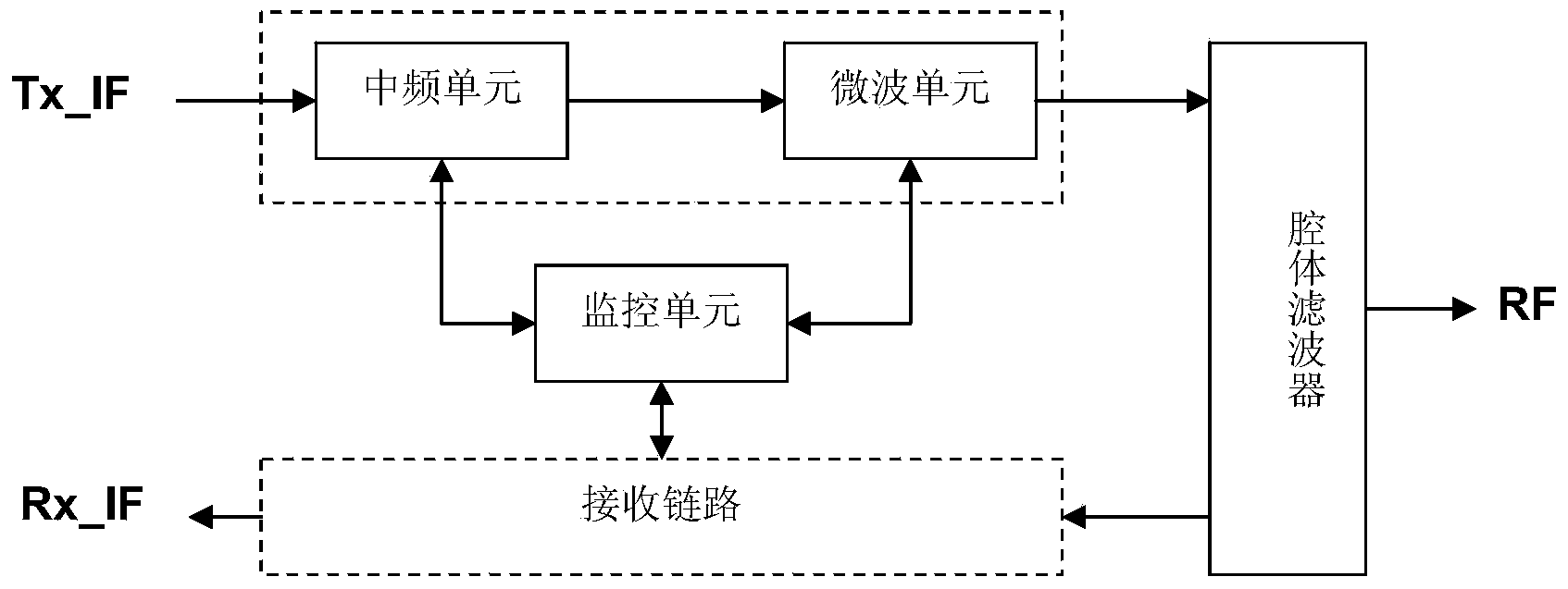
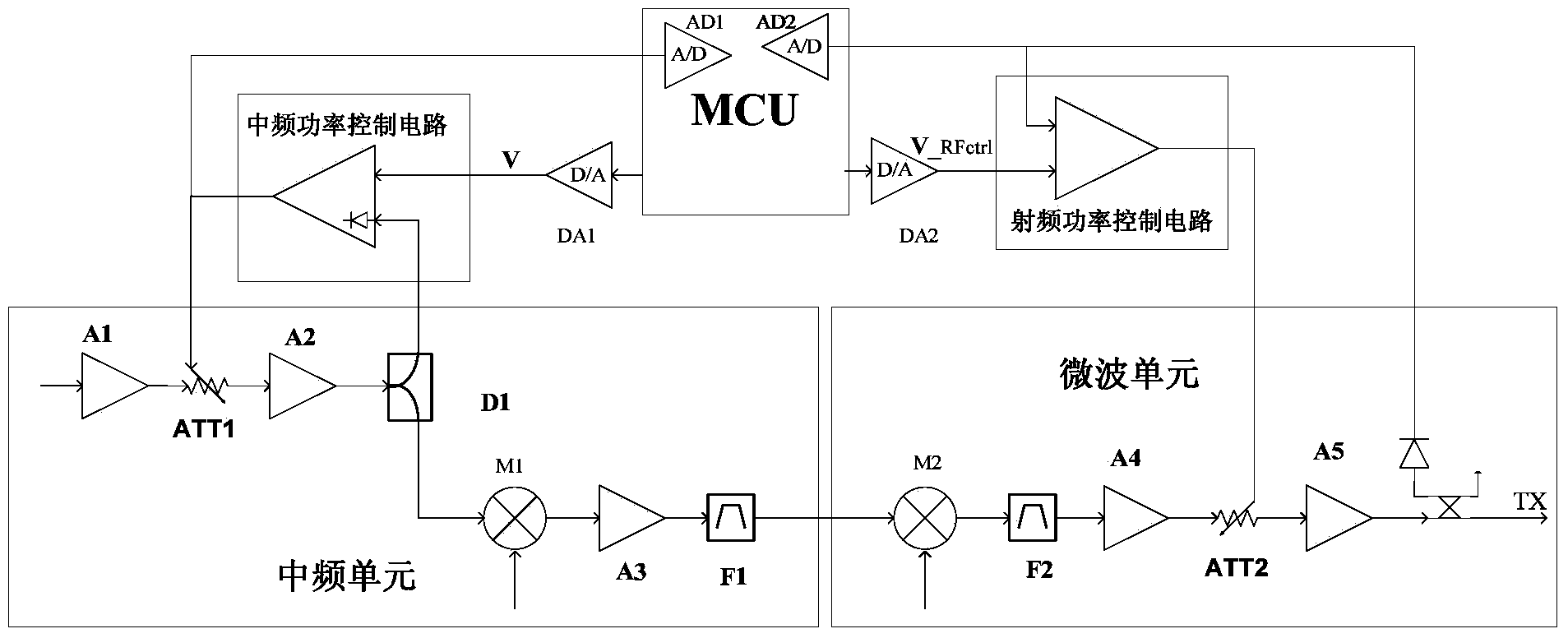
[0087] Such as figure 1 As shown, it is a block diagram of the main modules of the digital microwave transceiver. The digital microwave transceiver includes an intermediate frequency unit, a microwave unit, a monitoring unit, a receiving link and a cavity filter. The intermediate frequency unit includes an intermediate frequency power control circuit, a frequency mixing circuit, and a filter amplifier circuit. image 3 shown); the microwave unit includes a detection circuit, a microwave attenuator, a frequency mixing circuit, and a filter amplifier circuit. Cooperate with the RF power control circuit to realize the control of the RF power (such as image 3 shown); the monitoring unit includes an intermediate frequency power control circuit, a radio frequency power control circuit, etc., controls the transmission power through the MCU, and cooperates with the microwave module to form a closed-loop circuit for automatic control of radio frequency power (such as image 3 shown); ...


PUM


Abstract

The invention discloses a calibration method for the transmitted power of a digital microwave transceiver. The calibration method comprises the following steps of first generating a transmitted power calibration table according to transmitted power control voltages and actual radio frequency transmitted power which corresponds to the transmitted power control voltages and is transmitted by the microwave transceiver, second generating a channel calibration table, and thirdly correcting the transmitted power control voltage value in the transmitted power calibration table by using a channel correcting method. The invention further discloses a calibration circuit for achieving the calibration method for the transmitted power of the digital microwave transceiver. The calibration circuit comprises a microwave unit and a monitoring unit, and the microwave unit comprises a first power detection tube, a second power detection tube, a microwave amplifier and a microwave attenuator. The calibration circuit has the advantages of being high in batch production efficiency, high in calibration rate, high in transmitted power stability, simple in calibration method and the like.

Description

technical field [0001] The invention relates to a microwave radio frequency technology, in particular to a method for calibrating transmission power of a digital microwave transceiver and a calibrating circuit thereof. The invention is applicable to 5-42G digital microwave transceivers. Background technique [0002] The transmitter part of a digital microwave transceiver (radio frequency unit) is generally composed of multiple amplifiers, mixers, filters, and attenuators. Due to the poor consistency of microwave devices, it is greatly affected by temperature, causing the entire transmission link to The gain is unstable, which affects the accuracy of the output power of the transmitter (that is, the actual output power of the transmitter deviates greatly from the preset value); with the development of the communication industry, the operating frequency of digital microwave transceivers is getting higher and higher, and its passband Wider and wider, in such a wide frequency ra...

Claims


Application Information

Patent Timeline
IPC IPC(8): H04W52/04
Inventor 吴开华黄均明陈勇杨龙星孟晓君
Owner 波达通信设备(广州)有限公司
Why Eureka
Try Eureka