A diesel engine cylinder piston and a diesel engine using the combustion chamber

A cylinder piston and combustion chamber technology, applied in the directions of pistons, machines/engines, mechanical equipment, etc., can solve the problems of increased heat load on the bottom surface of the cylinder head, inability to effectively control fuel consumption, and restrict the rapid mixing of oil and gas, so as to reduce fuel consumption, avoid Higher thermal load and improved thermal efficiency

Active Publication Date: 2016-03-16
WEICHAI POWER CO LTD
View PDF7 Cites 2 Cited by
  • Summary
  • Abstract
  • Description
  • Claims
  • Application Information

AI Technical Summary

Problems solved by technology

However, limited by its own structure, the vortex in the groove area B is too strong. After passing through the arc ridge shunt, there is very little space for the upper part to be mixed with the upper air, which limits the rapid mixing of oil and gas. Only when the piston continues to go down Good mixing can only be achieved after exercise, and at this time, the best period of burning to reduce fuel consumption has passed
Obviously, although the combustion chamber improves SOOT emissions, it cannot effectively control fuel consumption at the same time
[0005] In addition, compared with the traditional "ω" shaped combustion chamber, figure 2 The combustion chamber shown increases the proportion of fuel mixed in the upper space, and the proportion of the fuel-air mixture near the bottom surface of the cylinder head increases during the combustion deceleration period. This also brings another problem, that is, the heat on the bottom surface of the cylinder head load rise
[0006] In view of this, it is urgent to optimize the performance of the existing combustion chamber to effectively control fuel consumption and overcome the problem of high thermal load on the bottom surface of the cylinder head.

Method used


Image

  • A diesel engine cylinder piston and a diesel engine using the combustion chamber
  • A diesel engine cylinder piston and a diesel engine using the combustion chamber
  • A diesel engine cylinder piston and a diesel engine using the combustion chamber

Examples


Embodiment Construction

[0027] The core of the invention is to optimize the structure of the combustion chamber of the cylinder piston of the diesel engine. By adjusting the direction of the upper vortex, on the basis of improving thermal efficiency and reducing fuel consumption, the problem of high thermal load on the bottom surface of the cylinder head can be effectively avoided. A detailed description will be given below in conjunction with the accompanying drawings of the description.

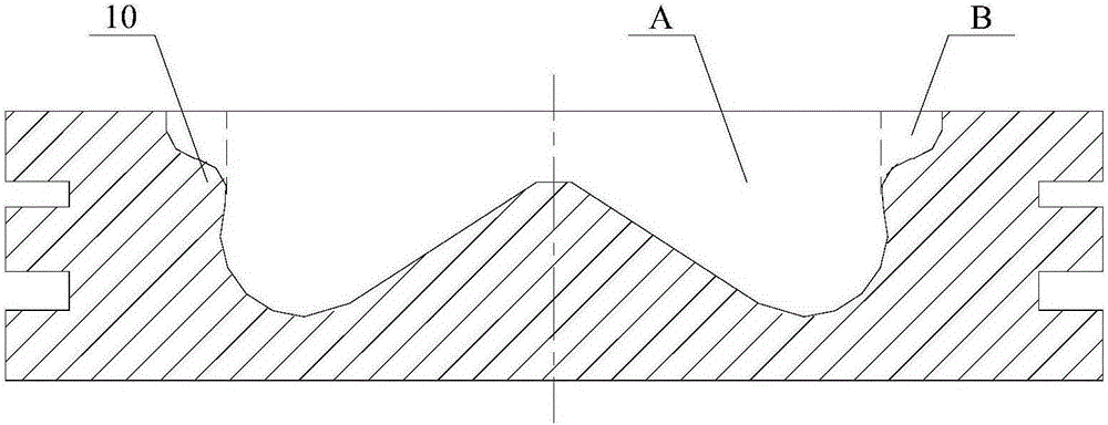
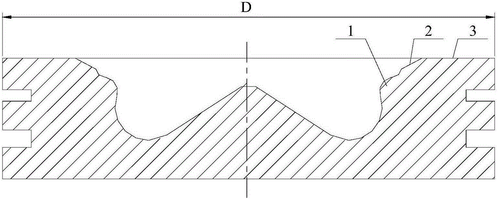
[0028] See image 3 and Figure 4 ,in, image 3 It is a schematic diagram of the axial section of the cylinder piston of the diesel engine described in the first embodiment, Figure 4 for image 3 A partially enlarged schematic view of the combustion chamber shown in .

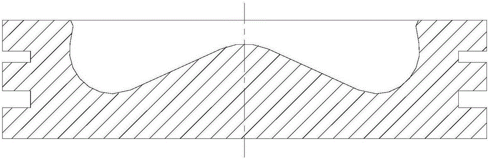
[0029] The top surface of the cylinder piston of the diesel engine has a combustion chamber whose axial cross-sectional outer profile is "ω"-shaped, and the basic shape of the combustion chamber is roughly the same as that of the prior art. T...


PUM


Abstract

The invention discloses a cylinder piston of an engine diesel. The top surface of the cylinder piston is provided with a combustion chamber with a W-shaped axial section external profile; the inner wall of the outer side of the combustion chamber is provided with an arc-shaped ridge which is extended into an accommodating cavity, and the combustion chamber is divided into an inside conventional region and a groove region by a tangent line formed by the highest point of radial protrusion of the arc-shaped ridge; the outer edge of the throat opening of the combustion chamber is provided with an end bevel, so as to form a buffer region communicated with the groove region; the external profile of the buffer region is of asymptotic trend change from the groove region to the top surface of the piston. By virtue of the structural optimization of the combustion chamber, the upper vortex trend can be adjusted, and the problem that the thermal load of the bottom surface of a cylinder cover can be effectively avoided on the basis of improving the thermal efficiency and reducing the oil consumption. On the basis, the invention further provides a diesel engine applying the cylinder piston.

Description

technical field [0001] The invention relates to the technical field of engines, in particular to a cylinder piston of a diesel engine and a diesel engine using the combustion chamber. Background technique [0002] With the continuous rise of fuel prices, in the competition of vehicle power systems, people began to pay more and more attention to the issue of engine energy saving and consumption reduction. At present, how to achieve lower fuel consumption on the basis of ensuring compliance with emission regulations has become a severe challenge for major engine manufacturers. [0003] The shape of the traditional diesel engine combustion chamber is roughly "ω" shape, please refer to figure 1 As shown, the figure shows the axial section view of a piston with a "ω"-shaped combustion chamber, and the volume of the cavity formed by the middle non-shaded part rotating around the axial direction of the combustion chamber is the combustion chamber cavity of the piston. The pit, ap...

Claims


Application Information

Patent Timeline
Patent Type & Authority Patents(China)
IPC IPC(8): F02F3/26
Inventor 李志杰马宝东王晓艳孙振宇
Owner WEICHAI POWER CO LTD
Why Eureka
Try Eureka