CAN (Controller Area Network) communication control device in converter and communication method

A CAN communication and control device technology, applied in the field of communication, can solve the problems of difficult unification of communication programs, susceptibility to interference, and high maintenance complexity of multi-axis converters

Active Publication Date: 2014-04-02
CSR ZHUZHOU ELECTRIC LOCOMOTIVE RES INST
View PDF4 Cites 15 Cited by
  • Summary
  • Abstract
  • Description
  • Claims
  • Application Information

AI Technical Summary

Problems solved by technology

However, each axis converter requires a CAN communication control board. Since the communication information, control information, status information, and fault information transmitted by each axis converter are different, this requires the transmission of messages between each CAN communication control board. The identifiers (ID) are different, which results in 16 different CAN communication programs for a sixteen-axis converter of an electric wheel vehicle, which makes it difficult to distinguish CAN communication programs in practical applications, and it is difficult to maintain in the later period. Programs are difficult to unify
[0006] The current multi-axis converter CAN communication scheme: each communication board uses a different program, which results in high complexity in the later maintenance of the multi-axis converter. In the early stage, different CAN communication schemes and related programs need to be developed. heavy workload
[0007] However, if the mine electric wheeler is controlled by hard wires, a large number of hard wires need to be arranged on the vehicle, and the vehicle control bus and strong electric cables are arranged together, which is easy to be interfered and is not conducive to system control, etc.

Method used


Image

  • CAN (Controller Area Network) communication control device in converter and communication method
  • CAN (Controller Area Network) communication control device in converter and communication method
  • CAN (Controller Area Network) communication control device in converter and communication method

Examples


Embodiment Construction

[0032] The embodiments of the present invention will be described in detail below in conjunction with the accompanying drawings, so as to fully understand and implement the process of how to apply technical means to solve technical problems and achieve technical effects in the present invention. It should be noted that, as long as there is no conflict, each embodiment of the present invention and each feature in each embodiment can be combined with each other, and the formed technical solutions are all within the protection scope of the present invention.

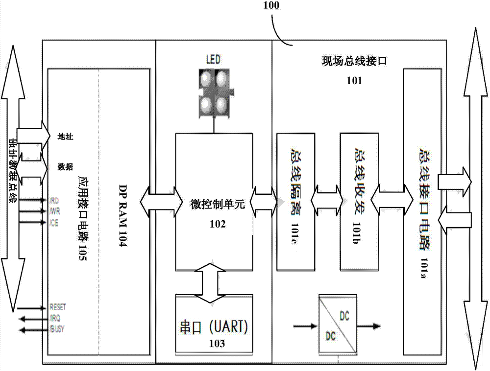
[0033] like figure 1 As shown, a CAN communication control device 100 used in a converter control system is shown. It includes: a CAN bus interface unit 101 , a micro control unit 102 and a serial bus interface unit 103 . The CAN bus interface unit 101 is used to connect the CAN communication control device 100 to the CAN field bus, so it is connected to the field bus to receive or send the CAN communication control device...


PUM


Abstract

The invention discloses a CAN (Controller Area Network) communication control device used in a control system of a converter. The CAN communication control device comprises a CAN bus interface unit and a microcontrol unit, wherein the CAN bus interface unit is connected with a field bus to receive or transmit messages to be delivered between the communication control device and other converter control devices on a bus network, and the messages are corresponding to a CAN standard protocol or user-defined field bus protocols; the microcontrol unit is connected with a CAN bus interface circuit to receive the messages sent by other remote converter control devices through the bus network, the messages are corresponding to the CAN standard protocol or user-defined field bus protocols, the messages are analyzed and treated according to inhouse configuration files and converted into parallel data information, and the configuration files are written on-line through a serial bus network through a serial bus interface unit connected with the microcontrol unit. The device can configurate different communication message IDs (identities) for the CAN communication control devices of different converters in a convenient and real-time mode, so that basic applications are unified.

Description

technical field [0001] The invention relates to the field of communication technology, in particular to a CAN communication control device and method in a converter. More specifically, it relates to a CAN communication control device and method in a converter of an electric wheel dump truck. Background technique [0002] CAN (Controller Area Network), that is, the controller area network, has attracted more and more attention because of its high performance, high reliability, and unique design. Many large companies abroad have adopted this technology in their products. CAN was originally designed by Germany's BOSCH company for vehicle monitoring and control systems. Modern automobiles are increasingly controlled by electronic devices, such as engine timing, fuel injection control, acceleration, braking control (ASC) and complex anti-lock braking system (ABS). [0003] At present, CAN, as a way of field bus communication, is also used in the electric drive system of mine e...

Claims


Application Information

Patent Timeline
Patent Type & Authority Applications(China)
IPC IPC(8): G05B19/418H04L12/40
CPCY02P90/02
Inventor 刘辉荣付如愿刘浩平周志宇梅文庆刘海涛蓝德劭杨大成
Owner CSR ZHUZHOU ELECTRIC LOCOMOTIVE RES INST
Why Eureka
Try Eureka