Driving connection device for motor and oil pump

A drive connection and oil pump technology, applied in the direction of electromechanical devices, electric components, electrical components, etc., can solve the problems of reducing the reliability of motor and oil pump movement, increasing the cumulative error of processing, accelerating the wear of spline teeth and teeth, and achieving improvement The effect of motion reliability, reduction of support bearings, and reduction of failure rate

Active Publication Date: 2014-04-02
NINGBO TENGLONG OUTDOOR IMPLEMENT
View PDF4 Cites 2 Cited by
  • Summary
  • Abstract
  • Description
  • Claims
  • Application Information

AI Technical Summary

Problems solved by technology

[0003] 1) Since the output shaft of the motor in the first structure or the input shaft of the oil pump in the second structure needs to be lengthened, in other words, they all need special processing and customization, so the versatility is poor and the processing cost is high;
[0004] 2) In addition, the rigidity of the elongated shaft decreases, and the cumulative error of machining increases, so that the accuracy of the shaft is poor;
[0005] 3) At the same time, after the shaft is lengthened, the stability of the movement decreases and the failure rate increases;
[0006] 4) The third type of structure causes the power input shaft of the oil pump to be connected to the motor shaft without fastening, and there is a gap between the teeth of the spline. In this way, when the motor and the oil pump operate, vibration will occur. On the one hand, there will be noise, on the other hand, it will also accelerate the wear between the spline teeth and reduce the movement reliability of the motor and oil pump

Method used


Image

  • Driving connection device for motor and oil pump
  • Driving connection device for motor and oil pump
  • Driving connection device for motor and oil pump

Examples


specific Embodiment approach 1

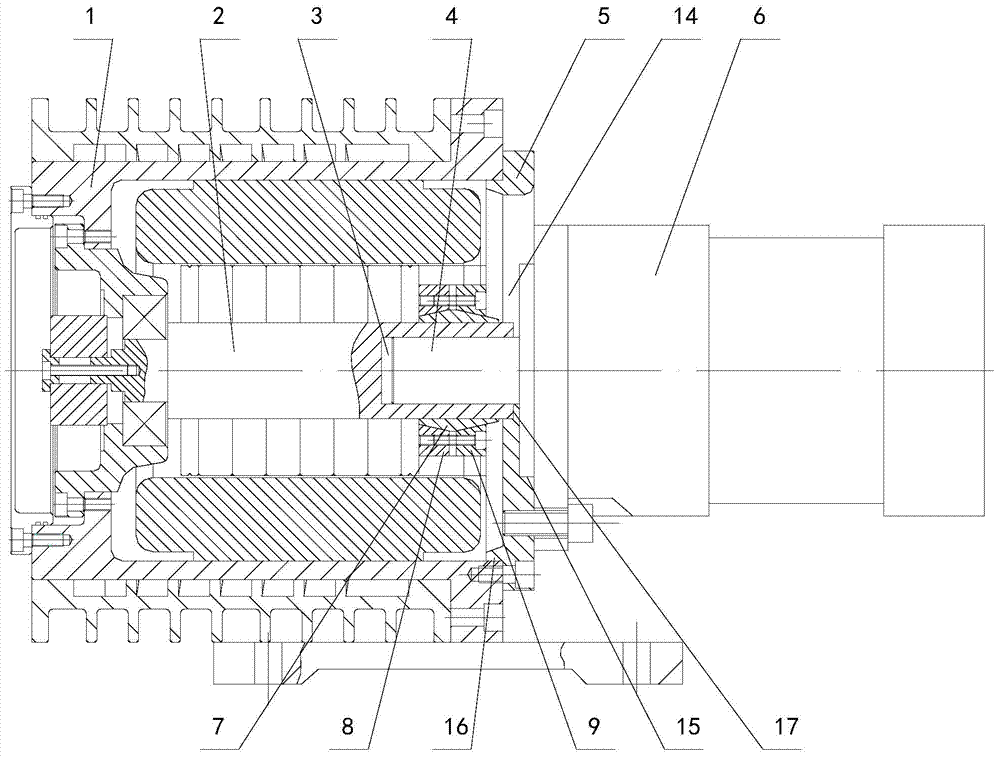
[0035] Depend on Figure 1 to Figure 5 It can be seen from the first structural schematic diagram of the drive connection device of the motor and oil pump of the present invention shown that it includes an end cover 5 connected to the motor 1 and the oil pump 6, the oil pump 6 is connected to the end cover 5, and the end cover 5 is connected to the motor 1 superior. It also includes a locking device that is located at one end of the motor 1 close to the end cover 5 and locks and connects the motor output shaft 2 and the power input shaft 4 of the oil pump 6. The end cover 5 has a locking device for disassembly and assembly. The insertion port 14.

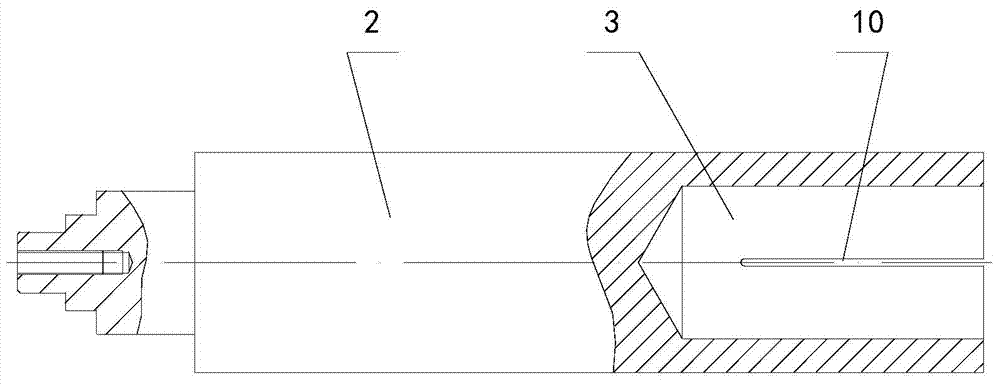
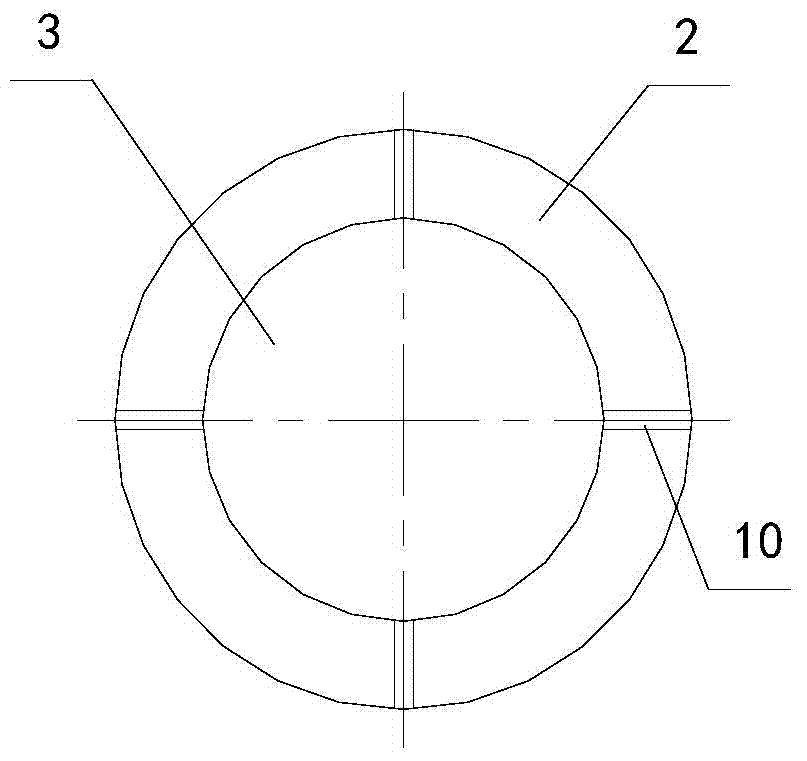
[0036] The power input shaft 4 of the oil pump 6 is located in one end of the motor output shaft 2 of the motor 1, and one end of the motor output shaft 2 has an axial mounting hole 3, and the power input shaft 4 of the oil pump 6 is sleeved in the mounting hole 3 , and at least one axial opening slot 10 is provided on the circumf...

specific Embodiment approach 2

[0040] Depend on Figure 6 and Figure 7 It can be seen from the second structural schematic diagram of the drive connection device of the motor and oil pump of the present invention shown that it includes an end cover 5 connected to the motor 1 and the oil pump 6, the oil pump 6 is connected to the end cover 5, and the end cover 5 is connected to the motor 1 superior. It also includes a locking device that is located at one end of the motor 1 close to the end cover 5 and locks and connects the motor output shaft 2 and the power input shaft 4 of the oil pump 6. The end cover 5 has a locking device for disassembly and assembly. The insertion port 14.

[0041] The power input shaft 4 of the oil pump 6 is located in one end of the motor output shaft 2 of the motor 1, and one end of the motor output shaft 2 has an axial mounting hole 3, and the power input shaft 4 of the oil pump 6 is sleeved in the mounting hole 3 , and at least one axial opening slot 10 is provided on the cir...

specific Embodiment approach 3

[0045] Depend on Figure 8 , Figure 9 and Figure 10 As can be seen from the third structural schematic diagram of the drive connection device of the motor and oil pump of the present invention, it includes an end cover 5 connected to the motor 1 and the oil pump 6, the oil pump 6 is connected to the end cover 5, and the end cover 5 is connected to the motor 1 superior. It also includes a locking device that is located at one end of the motor 1 close to the end cover 5 and locks and connects the motor output shaft 2 and the power input shaft 4 of the oil pump 6. The end cover 5 has a locking device for disassembly and assembly. The insertion port 14.

[0046] The locking device means that the peripheral wall of the mounting hole 3 on the motor output shaft 2 has at least one notch 26 penetrating through the wall thickness and extending axially, and the motor output shaft 2 at the notch 26 is locked and connected by a locking bolt 27 .

[0047] In this embodiment, there ar...


PUM


Abstract

The invention discloses a driving connection device for a motor and an oil pump. The driving connection device comprises an end cover (5) connected with the motor (1) and the oil pump (6), wherein the oil pump (6) is connected onto the end cover (5); the end cover (5) is connected onto the motor (1); the driving connection device further comprises a locking device which is located in the motor (1), close to one end of the end cover (5), and connects an output shaft (2) of the motor to a power input shaft (4) of the oil pump (6) in a locking manner; and a plug-in mounting port (14) for mounting and dismounting the locking device is formed in the end cover (5). With the adoption of the structure, the power input shaft of the oil pump is in standard delivery configuration, and is not required to be lengthened to extend into the motor, that is to say the power input shaft of the oil pump is not required to be processed and customized specially, so that the production cost is greatly lowered; the generality of the device is improved; at the same time, the rigid strength of the shaft is greatly improved; and the processing cumulative error is reduced, so that the dimensional precision of the shaft is improved.

Description

technical field [0001] The invention relates to the technical field of motors, in particular to a drive connection device for a motor and an oil pump. Background technique [0002] The motor and the oil pump are two commonly used accessories in the mechanical field. Usually, the power input of the oil pump is driven by the motor, that is to say, the motor and the oil pump are connected through a drive connection device. In the prior art, there are usually several ways for this connection device. The first structure is to extend the output shaft of the motor and extend it into the oil pump so that the motor shaft and the oil pump shaft are integrated into one shaft. The second structure is to The input shaft of the oil pump is lengthened and stretched into the motor, so that the oil pump shaft and the motor shaft are also integrated into one shaft. The third kind of standard is that the power input shaft of the oil pump is connected with the motor shaft through a spline stru...

Claims


Application Information

Patent Timeline
Patent Type & Authority Applications(China)
IPC IPC(8): H02K7/14H02K5/04
Inventor 刘坚
Owner NINGBO TENGLONG OUTDOOR IMPLEMENT
Why Eureka
Try Eureka