Self-suction pipeline mixing reactor

A pipeline mixing, self-priming technology, applied in fluid mixers, chemical/physical/physical-chemical nozzle reactors, mixers, etc., can solve the problem of low mixing efficiency, large reactor volume, and short effective reaction time, etc. problem, to achieve the effect of reducing physical length, good technical effect, and shortening mixing time

Active Publication Date: 2014-04-09
CHINA PETROCHEMICAL CORP +1
View PDF6 Cites 14 Cited by
  • Summary
  • Abstract
  • Description
  • Claims
  • Application Information

AI Technical Summary

Problems solved by technology

[0005] The technical problem to be solved by the present invention is that the prior art has the problems of low mixing e

Method used


Image

  • Self-suction pipeline mixing reactor
  • Self-suction pipeline mixing reactor

Examples


Embodiment 1

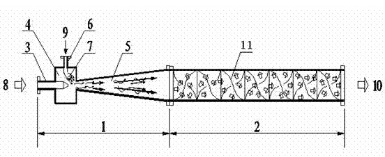
[0019] Adopt the self-priming pipeline mixing reactor of the present invention to process the wastewater containing cefazolin antibiotic components, with a treatment capacity of 5m 3 / h. Due to the dispersing effect of the distributor, the 3% by weight sodium hydroxide dilute solution is sucked through the fluid distributor, forms dozens of small liquid streams through the small holes of the distributor and enters the waste water fluid, and then passes through the subsequent pipeline The mixer is further mixed evenly, and the pH value of the effluent is stable above 13, which achieves the purpose of pretreatment, and then directly enters the subsequent biochemical treatment station for further treatment.

[0020] The total length of the mixing reactor is 2.6m, the diameter of the mixing section is 100mm, the built-in corrugated packing, and the effective flow area is 50%. The ratio of the lengths of the suction cavity section 4, the diffusion section 5 and the mixing section ...

Embodiment 2

[0023] The wastewater treatment process is the same as in Example 1, and the treatment capacity requirement reaches 10m 3 / h. The total length of the entire suction mixing reactor is 2.6m, the diameter of the mixing section is 125mm, and corrugated packing is built in, and the effective flow area is 50%. The length ratio of the suction chamber section 4, the diffusion section 5 and the mixing section 2 is 1:3:15, the diameter of the fluid inlet pipe 3 is 40mm, and the inner diameter of the suction chamber section 4 is 125mm, the ratio of the two is 40:125 = 3, the suction The diameter of the logistics pipeline 6 is 15 mm, and the ratio of the inner diameter to the suction cavity section 4 is 15:125=1:8.3.

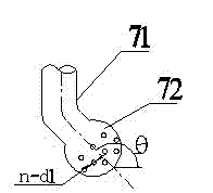
[0024] The position where the fluid distributor 7 penetrates into the suction chamber section 4 is 1 / 3 of the inner diameter of the suction chamber section 4 . The hemispherical hollow cavity 72 of the fluid distributor 7 is provided with n=60 circular holes, the diameter ...

Embodiment 3

[0027] Same as Example 1, the wastewater treatment capacity is required to reach 15m 3 / h. The total length of the entire suction mixing reactor is 3.6 m, the diameter of the mixing section is enlarged to 150 mm, with built-in corrugated packing, and the effective flow area is 50%. The length ratio of the suction chamber section 4, the diffusion section 5 and the mixing section 2 is 1:4:20, the diameter of the fluid inlet pipe 3 is 40mm, and the inner diameter of the suction chamber section 4 is 150mm, the ratio of the two is 40:150=1:3.75 , the diameter of the suction flow pipeline 6 is 25mm, and the inner diameter ratio of the suction chamber section 4 is 1:6.

[0028] The position where the fluid distributor 7 penetrates into the suction chamber section 4 is 1 / 4 of the inner diameter of the suction chamber section 4 . The hemispherical hollow cavity 72 of the fluid distributor 7 is provided with n=70 circular holes, the diameter of the circular holes is d=4mm, and the inc...


PUM


Abstract

The invention relates to a self-suction pipeline mixing reactor, which solves the problems of low mixing efficiency, short effective reaction time and large volume of the reactor. The self-suction pipeline mixing reactor comprises a suction segment 1 and a mixing segment 2 along a fluid flow direction in order; wherein the suction segment 1 comprises a fluid inlet pipeline 3, a suction chamber segment 4 and an expansion segment 5. The fluid inlet pipeline 3 stretches into the suction chamber segment 4, the end is contracted to a conical shape; a suction flow pipeline 6 is provided on the pipe wall of the suction chamber segment 4, and a fluid distributor 7 is provided on the end of the suction flow pipeline 6 deeply stretches into the suction chamber segment 4; a diversion baffle plate is provided on the pipe wall of the mixing segment 2; the axis of the fluid inlet pipeline 3, the suction chamber segment 4, the expansion segment 5 and the mixing segment 2 are superposed along the fluid flow direction. The technical scheme better solves the problems, and the self-suction pipeline mixing reactor can be used in an industrial production for treating waste water from the medicines production.

Description

technical field [0001] The invention relates to a self-priming pipeline mixing reactor with a distributor. Background technique [0002] The Venturi effect means that a low pressure will be generated near a high-speed flowing fluid, resulting in adsorption. This phenomenon is named after its discoverer, the Italian physicist Giovanni Battista Venturi, so it is called the Venturi effect. The device made according to this effect is also called Venturi tube. Venturi tubes are currently widely used in industrial fields, such as water jet vacuum pumps used to generate vacuum, which use the Venturi principle to generate vacuum. [0003] The pipe mixer is a long and thin pipe with a continuous and irregular diversion baffle in the middle. When more than two streams of fluid pass through, under the action of the baffle, the forward fluid will constantly change its flow due to resistance. Direction, local formation of turbulence and turbulence, impact between fluids, etc., so that...

Claims


Application Information

Patent Timeline
IPC IPC(8): B01J19/26B01F5/02C02F1/66
Inventor 杨军李陈江
Owner CHINA PETROCHEMICAL CORP
Why Eureka
Try Eureka