
Composite reinforced roadbed and construction method

A technology of roadbed and water permeability, applied in the direction of roads, roads, buildings, etc., to achieve the effect of strong anti-corrosion ability, enhancing overall performance and reducing settlement

Inactive Publication Date: 2014-04-09
SHANDONG UNIV
View PDF7 Cites 14 Cited by
  • Summary
  • Abstract
  • Description
  • Claims
  • Application Information

AI Technical Summary

Problems solved by technology

[0003] In order to solve the above problems, the present invention proposes a composite reinforced roadbed and a construction method, which helps to alleviate the problem of "black pollution" caused by waste tires, recycles and reuses waste, and protects the environment

Method used


Image

  • Composite reinforced roadbed and construction method
  • Composite reinforced roadbed and construction method

Examples


example 1

[0054] In a contract section of Qinglin Road, this method is used to treat the culvert foundation and subgrade to control settlement and reduce the hazard of vehicle jumping. The elevation of the subgrade is 6.5m, the diameter of the permeable concrete pile is 0.5m, the length of the pile under the culvert is 8m, and the treatment length of the subgrade part is 30m , divided into three zones A, B and C, each zone is 10m long, the piles in zone A are 11m long, the piles in zone B are 9m long, and the piles in zone C are 7m long. They are arranged in an equilateral triangle with a pile distance of 1.8m. Above, the gravel filling height is 20cm (tires and gravel are only arranged on the subgrade). The treatment results show that 3 years after the completion of the culvert and subgrade, the post-construction settlement of the culvert was 4.1cm, and the differential settlement compared with the bridge head was 1.8cm. Under the influence of heavy rain and heavy traffic load, there wa...

example 2

[0056] In a contract section of Shandong Provincial Highway S336, this method is used to treat the subgrade at the bridgehead to reduce the hazards of vehicle jumping at the bridgehead. The subgrade elevation of this section is 5.5m, the diameter of the permeable concrete pile is 0.5m, and the treatment length of the subgrade is 30m. It is divided into three types: A, B and C. Each area is 10m long. The piles in area A are 10m long, the piles in area B are 8m long, and the piles in area C are 6m long. They are arranged in an equilateral triangle with a pile distance of 1.5m. Tires are arranged above permeable concrete piles. . The treatment results show that after 5 years of highway operation, the differential settlement between the bridge head and the roadbed is 1.5cm. Under the influence of heavy rain and heavy traffic load, there is no slope collapse phenomenon, and the water content of the subgrade above the gravel cushion is significantly higher than that of the lower part...


PUM


Abstract

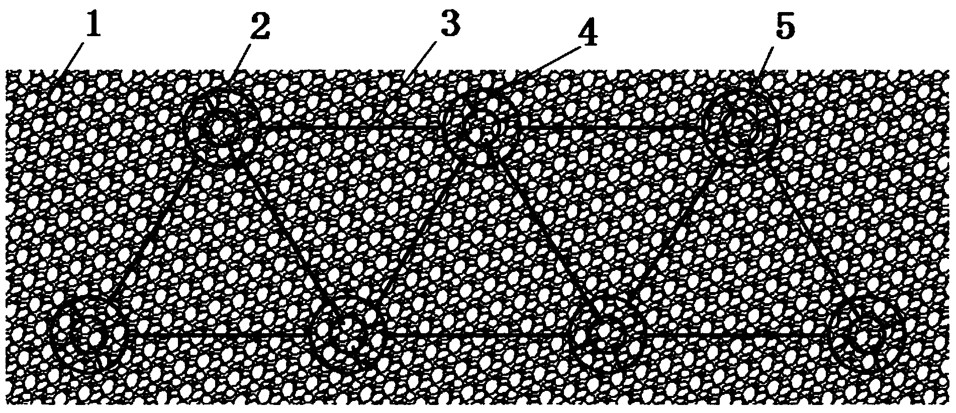
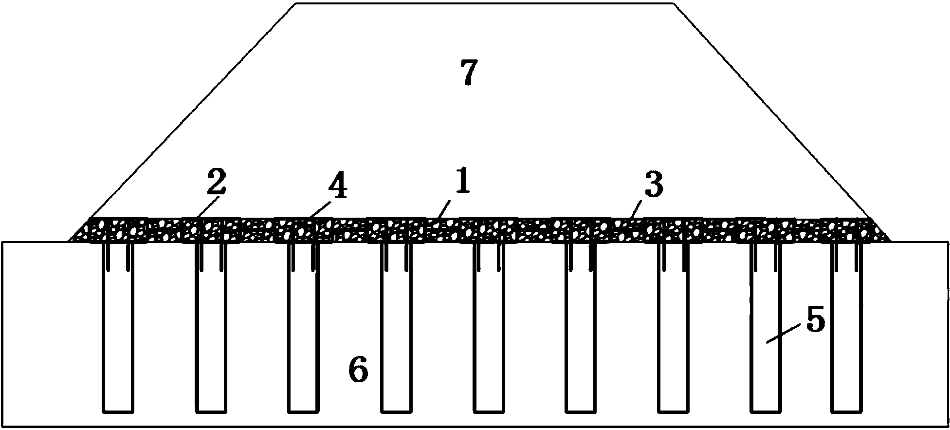
The invention discloses a composite reinforced roadbed and a construction method. The composite reinforced roadbed comprises water-permeable concrete piles, waste tires, connection pieces and gravels, wherein the water-permeable concrete piles are sequentially poured to peaks of triangles according to the shapes of equilateral triangles; each longitudinally cut waste tire is fixed on a steel bar of each water-permeable concrete pile; the water-permeable concrete piles are connected through the connection pieces in sequence and are buried on the roadbed; the equilateral triangles and the tires are filled with the gravels; the structure is filled with the soil roadbed. According to the composite reinforced roadbed, the waste tires are arranged at the bottom of the roadbed and replace part of the soil body; compared with the friction force in the soil body, the friction force between the soil body and the waste tires or the friction force caused by indirect contact between the gravels and the tires is obviously increased; in spite of cohesive soil or non-cohesive soil, the cohesive force of the soil body or the inner friction angle of the soil body can be increased; the stability of a slope of the roadbed is improved.

Description

technical field [0001] The invention relates to the field of road engineering, in particular to a composite reinforced roadbed and a construction method. Background technique [0002] In recent years, with the gradual improvement of people's living standards and the rapid development of the logistics industry, the number of private cars and trucks in my country has increased year by year. The increase in the number of vehicles has driven the development of the economy. At the same time, the consumption and wear of automobile tires has also produced a lot of garbage - waste tires. The "black pollution" formed by more and more waste tires is threatening the living environment of all human beings. At present, there are many ways to recycle waste tires as resources. The main ways of reuse are: heat energy utilization, thermal decomposition, production of reclaimed rubber, etc. Among them, the application of waste tires in road construction is the research and application of vari...

Claims


Application Information

Patent Timeline
Patent Type & Authority Applications(China)
IPC IPC(8): E01C3/04
Inventor 宋修广于一凡葛智张宏博厉超吴建清
Owner SHANDONG UNIV
Learn More