
Parallel torch support tower

A technology for supporting towers and torches, applied to towers, building types, buildings, etc., can solve the problems of torch installation and disassembly, large steel consumption, and small lateral rigidity, so as to achieve smooth loading and unloading of torches and reduce steel consumption , reducing the effect of deformation

Active Publication Date: 2015-11-04
铖熤科技(山西)有限责任公司
View PDF5 Cites 1 Cited by
  • Summary
  • Abstract
  • Description
  • Claims
  • Application Information

AI Technical Summary

Problems solved by technology

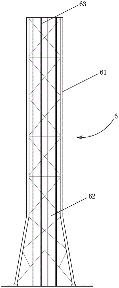
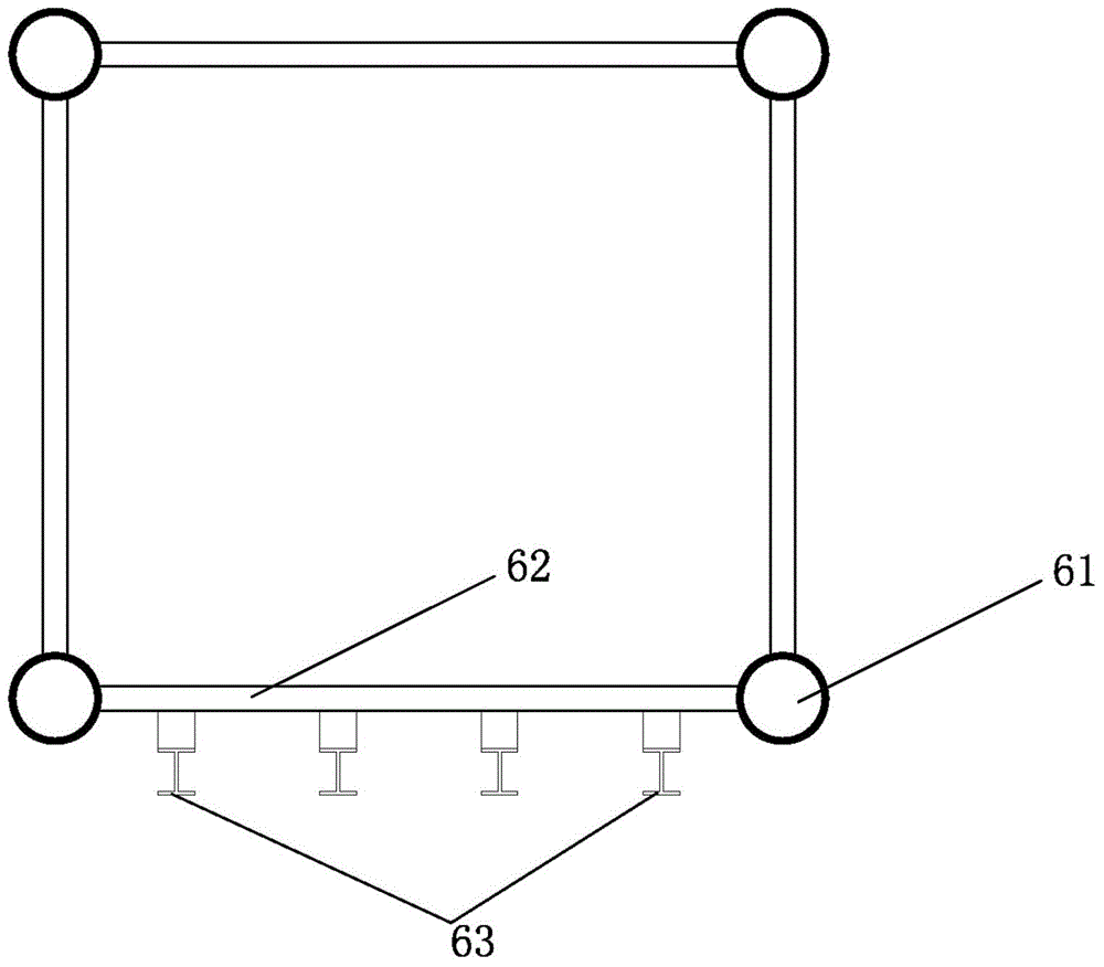
[0005] (1) The fulcrum of the track is on the beam. Due to the large distance between the beams, the span of the torch lifting track is also large. In addition, the lateral stiffness of the beam itself is very small, so the deformation of the torch lifting track is difficult to control. Torch installation and Jamming often occurs during disassembly;
[0006] (2) The surface width of the torch lifting track that can be arranged is only the distance between adjacent tower columns. The number of torches that can be installed is small and cannot be expanded. If there are more torch installation needs in the future, only new towers can be built;
[0007] (3) The stress on the components of the torch support tower is unreasonable, and the volume of a single component is large, which brings great inconvenience to manufacturing, transportation and installation, and the overall steel consumption is huge

Method used


Image

  • Parallel torch support tower
  • Parallel torch support tower
  • Parallel torch support tower

Examples


Embodiment 1

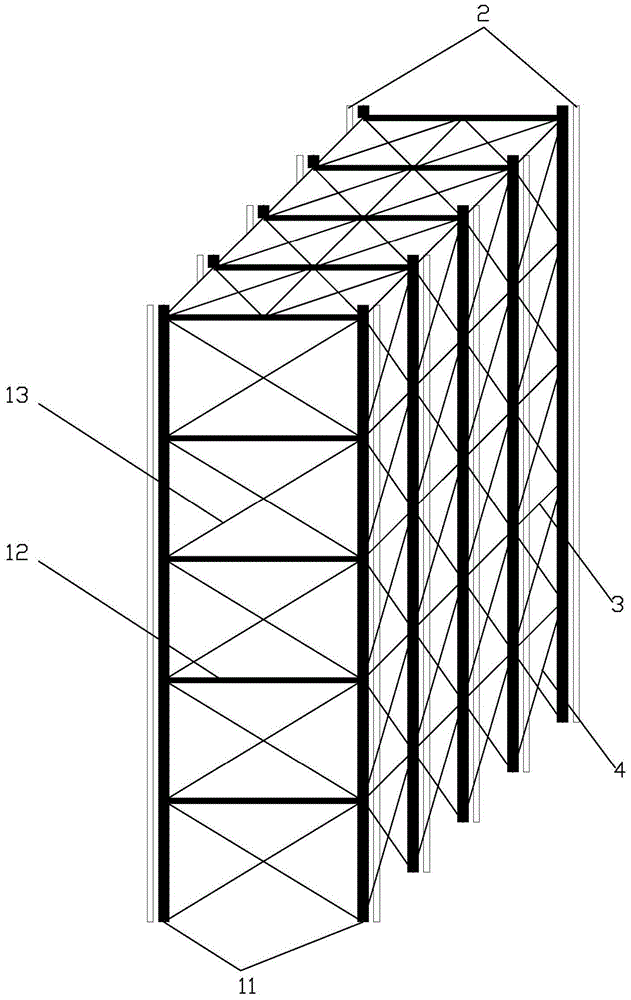
[0033] Such as image 3 , Figure 4 and Figure 5 As shown, the side-by-side torch support tower includes a torch support unit 1, a tower column 11, a horizontal support 12 between columns, a cross support 13 between columns, a torch lifting track 2, a unit connecting cross bar 3, and a unit connecting oblique bar 4 , Unit connection interface 5 . The torch support unit 1 is composed of two sets of tower columns 11 perpendicular to the ground and inter-column horizontal supports 12 and inter-column cross supports 13. The shape of the torch support unit 1 is rectangular.

[0034] Torch lifting rails 2 are installed at both ends of the torch support unit 1 .

[0035] Unit connection interfaces 5 are arranged on both sides of the torch support unit 1, and each group of torch support units 1 is connected into a spatial overall structure through the unit connection cross bar 3 and the unit connection oblique bar 4. The outer reserved unit of the torch support unit 1 is connecte...

Embodiment 2

[0040] as attached Figure 6 As shown, the structure and beneficial effects of this embodiment are basically the same as those in Example 1, the difference being that one group of the two groups of tower columns 11 that make up the torch support unit 1 is perpendicular to the ground, and the other group is inclined, and the torch support unit The shape of 1 is similar to a right triangle, and the torch lifting track 2 is installed on the end of the torch support unit 1 perpendicular to the ground.


PUM


Abstract

The invention relates to a side-by-side type torch supporting tower which comprises torch supporting units, unit connecting cross rods and unit connecting oblique rods. The torch supporting units are arranged in parallel and perpendicular to the ground, the unit connecting cross rods and the unit connecting oblique rods are arranged between adjacent torch supporting units, and the torch supporting units are connected to be a spatial overall structure. According to the side-by-side type torch supporting tower, all torch lifting tracks are fixed on tower columns, rigidity of the torch lifting tracks is greatly improved, deformation of the torch lifting tracks is reduced, and torches can be assembled and disassembled more smoothly. Torch loads directly act on the main stress structure, the structure is more reasonable, the torch supporting tower is convenient to manufacture, convey and mount, and steel using amount can be lowered.

Description

technical field [0001] The invention relates to a torch support tower of a petrochemical system and a smelting system, in particular to a side-by-side torch support tower equipped with a torch lifting rail. Background technique [0002] In the process of petroleum refining, it contains a large amount of hydrogen, methane, ethane, propane, propylene, sulfur, hydrogen sulfide, mercaptan and other gases containing flammable, explosive, toxic and dangerous components. Therefore, in the actual production process, The torch must be used to balance the above-mentioned flammable, explosive, toxic and dangerous components that may appear at any time. The torch is one of the important safety measures in petroleum processing, which can directly affect the smooth operation of the device and is an important safety balance facility. , is also one of the landmark buildings of petroleum refining enterprises. [0003] In order to save space and investment, usually multiple flares share one ...

Claims


Application Information

Patent Timeline
Patent Type & Authority Patents(China)
IPC IPC(8): E04H12/00
Inventor 王勇廖朝兵刚建
Owner 铖熤科技(山西)有限责任公司
Learn More