Current lead structure for superconducting magnet

A technology of current leads and superconducting magnets, applied in superconducting magnets/coils, magnetic objects, circuits, etc., can solve the problems of reducing containers, increasing heat leakage, disadvantages, etc., and achieve the effect of reducing the number of insertions and withdrawals

Active Publication Date: 2014-04-09
ALLTECH MEDICAL SYST
View PDF4 Cites 8 Cited by
  • Summary
  • Abstract
  • Description
  • Claims
  • Application Information

AI Technical Summary

Problems solved by technology

The current general application is to separate the coolant channel from the current channel, and even the positive and negative current channels. This not only requires multiple jacks on the console, but also increases heat leakage, which is not conducive to maintaining low temperature and lowering the container. The evaporation rate of the coolant is medium, and the operation is relatively cumbersome: after the coolant is filled, the catheter needs to be taken out, and then the positive and negative current guide rods are inserted into the magnetization operation, and the positive and negative current guide rods are pulled out after the end ; If it is necessary to release energy or extract coolant, the above operations must be repeated, and the efficiency is not high

Method used


Image

  • Current lead structure for superconducting magnet
  • Current lead structure for superconducting magnet
  • Current lead structure for superconducting magnet

Examples


Embodiment Construction

[0021] The present invention will be further described below in conjunction with the accompanying drawings and specific embodiments.

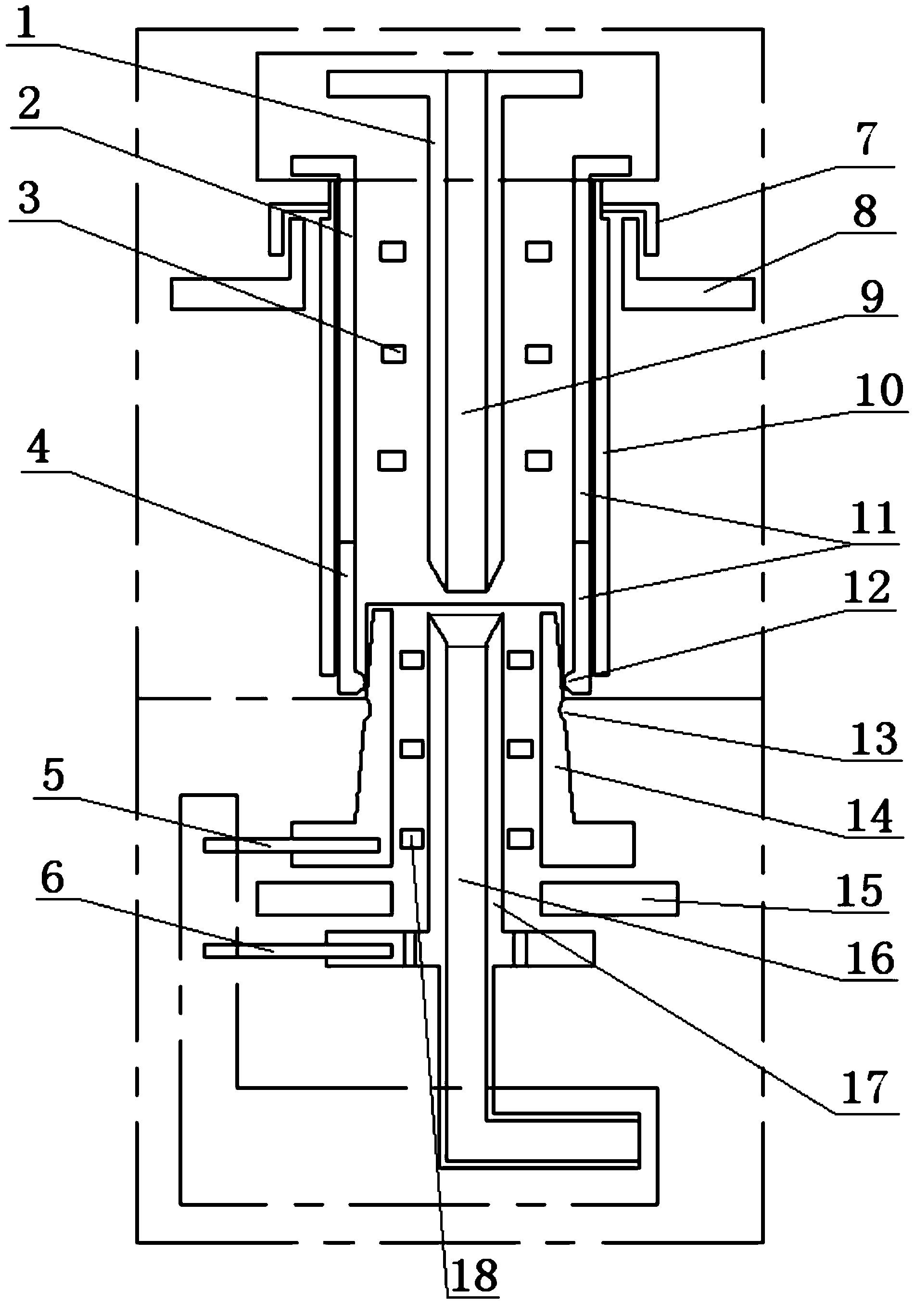
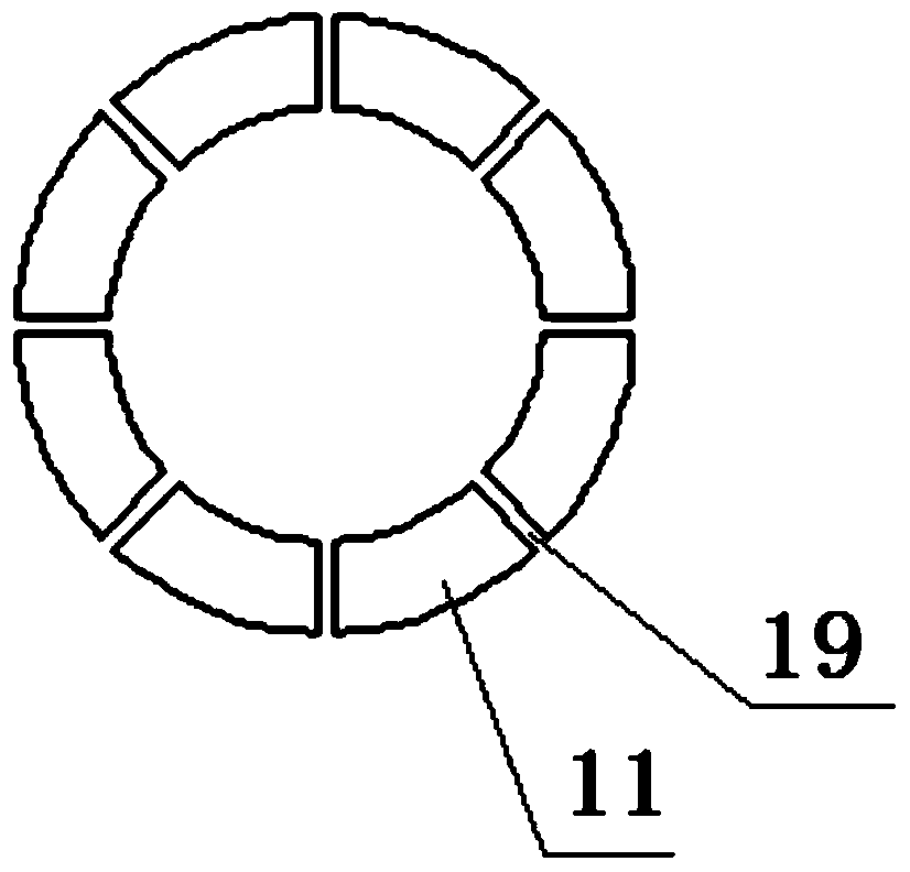
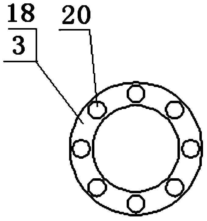
[0022] A current lead structure for a superconducting magnet includes a moving part and a fixed part axially butted; the fixed part includes a first fixed electrode 14 and a second fixed electrode 17 insulated from each other, the first fixed electrode 14 is in the shape of a hollow cylinder, and The two fixed electrodes 17 are hollow cylindrical in shape and arranged concentrically with the first fixed electrode 14, and the inner space of the second fixed electrode 17 is a coolant receiving channel 16; the moving part includes a first moving electrode 11 and a second moving electrode 1 insulated from each other , the shape of the first moving electrode 11 is a hollow cylinder, the shape of the second moving electrode 1 is hollow and concentric with the first moving electrode 11, and the inner space of the second moving electrode 1 is the coolan...


PUM


Abstract

The invention discloses a current lead structure for a superconducting magnet, relates to a current lead structure, and provides a current lead structure for a superconducting magnet, wherein electric power can through the current lead structure, and a coolant can also pass through the current lead structure. The current lead structure for the superconducting magnet comprises a moving part and a fixed part which are axially butted, wherein the fixed part comprises a first fixed electrode and a second fixed electrode which are mutually insulated and arranged in an embedding way, a space inside the second fixed electrode is a coolant receiving channel; the moving part comprises a first moving electrode and a second moving electrode which are mutually insulated and embedded and arranged, a space inside the second moving electrode is a coolant guiding channel; and the end part of the first moving electrode and the end part of the first fixed electrode are conducted through contact, the end part of the second moving electrode and the end part of the second fixed electrode are conducted through contact and sealed, and the coolant guiding channel is communicated with a coolant receiving channel. Magnetizing and bleeding a superconducting coil by connecting a power supply and adding or reducing a coolant in a low temperature closed container holding the superconducting coil can be realized through the current lead structure.

Description

technical field [0001] The invention relates to a current lead structure, in particular to a current lead structure used to energize a superconducting magnet. Background technique [0002] At present, the application of high-field superconducting MR magnets in the domestic medical imaging industry is very common. The basic principle is to use the superconducting properties of some alloy materials at ultra-low temperature (usually liquid helium temperature), and place the coil wound with this type of wire in a closed container, through cooling, vacuum insulation and other The thermal insulation method creates a relatively stable low-temperature environment, so that the coils located in it can maintain a superconducting state. But in fact, the so-called cryogenic container is not strictly sealed. It needs to be filled with coolant (liquid nitrogen, liquid helium, etc.) The external circuit leaks energy, so it is necessary to leave a coolant channel and a positive and negativ...

Claims


Application Information

Patent Timeline
Patent Type & Authority Applications(China)
IPC IPC(8): H01F6/06H01F6/04G01R33/3815
Inventor 贾敬朝张涛
Owner ALLTECH MEDICAL SYST
Why Eureka
Try Eureka