
Electronic component and manufacturing method thereof

A technology of electronic components and manufacturing methods, which is applied in the direction of assembling printed circuits with electrical components, transformer/inductor shells, transformer/inductor coils/windings/connections, etc., can solve the problem of small current and low magnetic permeability of magnetic core powder. , Unable to high power, high current, high inductance performance at the same time showing better performance, etc.

Inactive Publication Date: 2014-04-09
黄伟嫦
View PDF3 Cites 17 Cited by
  • Summary
  • Abstract
  • Description
  • Claims
  • Application Information

AI Technical Summary

Problems solved by technology

However, most of the small-sized chip electronic components in the current market have low inductance, low current, poor reliability, high temperature rise, and poor anti-EMI effect.
Due to conventional shielded electronic components or unshielded electronic components, high power, high current, and high inductance performance cannot be displayed at the same time.
At present, there are integrated electronic components using powder die-casting, but due to the generally low magnetic permeability of the magnetic core powder used in powder die-casting integrated electronic components, the performance is still limited by high current and low inductance.

Method used


Image

  • Electronic component and manufacturing method thereof
  • Electronic component and manufacturing method thereof
  • Electronic component and manufacturing method thereof

Examples


Embodiment Construction

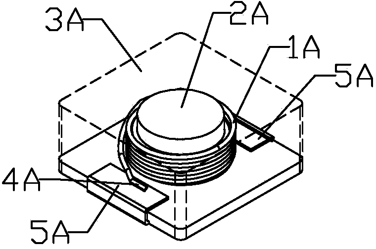
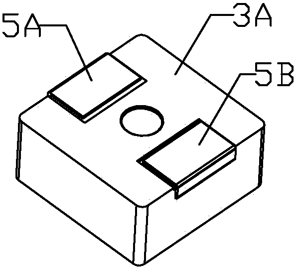
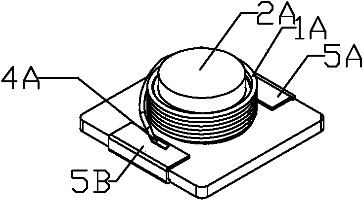
[0071] The electronic component and its manufacturing method of the present invention will be further described in detail below with reference to the accompanying drawings.

[0072] Such as Figure 1 to Figure 40 As shown, the present invention is an electronic component, which is characterized in that: the electronic component includes an inner core and an outer cladding layer (3A, 3B, 3C, 3D, 3E, 3F, 3G), and the inner core is located In cladding; said inner core comprising coil windings (1A, 1B, 1C, 1D, 1E, 1F, 1G) and coil assembly, printed circuit and printed circuit assembly comprising a body and extensions from said body (4A, 4B, 4C, 4D, 4E, 4F, 4G, 4H, 4I, 4J, 4L, 4M, 4N) and extensions are connected to terminals (5A, 5B, 5C, 5D, 5E, 5F) by welding or spot welding , 5G), the formed electrode; the outer cladding layer is to adopt a pressurized method to embed the inner core in the slurry mixture material by extrusion molding or casting or embedded casting, so that the ...


PUM


Abstract

The invention discloses an electronic component. The electric component is characterized by comprising an inner core and an outer wrapping layer, wherein the inner core is located in the outer wrapping layer; the inner core comprises a combination of a coil winding and a coil and a combination of print circuits and further comprises a main body and an electrode formed due to the fact that an extending portion from the main body is connected with a terminal through welding or point welding; the outer wrapping layer is formed in the mode that the inner core is compressed to be embedded in a pulpy mixture material in a squeezing forming mode or a casting mode or an embed casting mode so that the pulpy mixture material tightly wraps the inner core and heating curing is carried out, and the surface of the outer wrapping layer is sleeved with a metal shell or a plastic shell. The electronic component and the manufacturing method have the advantages that manufacturability and performance are improved.

Description

technical field [0001] The invention relates to an electronic component and its manufacturing method. Background technique [0002] With the development of electronic technology towards high frequency and miniaturization, electronic components are constantly required to carry out matching technological innovations. However, most of the small-sized chip electronic components in the current market have low inductance, low current, poor reliability, high temperature rise, and poor anti-EMI effect. Because conventional shielded electronic components or unshielded electronic components cannot simultaneously display better effects of high power, high current, and high inductance. At present, there are integrated electronic components using powder die-casting, but due to the generally low magnetic permeability of the magnetic core powder used in powder die-casting integrated electronic components, the performance is still limited by high current and low inductance. Therefore, the...

Claims


Application Information

Patent Timeline
IPC IPC(8): H01F17/04H01F27/02H01F27/28H05K3/30
Inventor 黄伟嫦
Owner 黄伟嫦
Learn More