Intelligent power module manufacturing method and intelligent power module

A technology of an intelligent power module and a manufacturing method, which is applied in the manufacture of semiconductor/solid-state devices, electrical components, and electrical solid-state devices, etc., can solve problems such as difficulty in observing and measuring height, damage to circuit wiring and circuit components, short-circuit or open-circuit, etc. Guaranteed long-term reliability, improved assemblability, improved compactness

Active Publication Date: 2014-04-09
美垦半导体技术有限公司
View PDF6 Cites 12 Cited by
  • Summary
  • Abstract
  • Description
  • Claims
  • Application Information

AI Technical Summary

Problems solved by technology

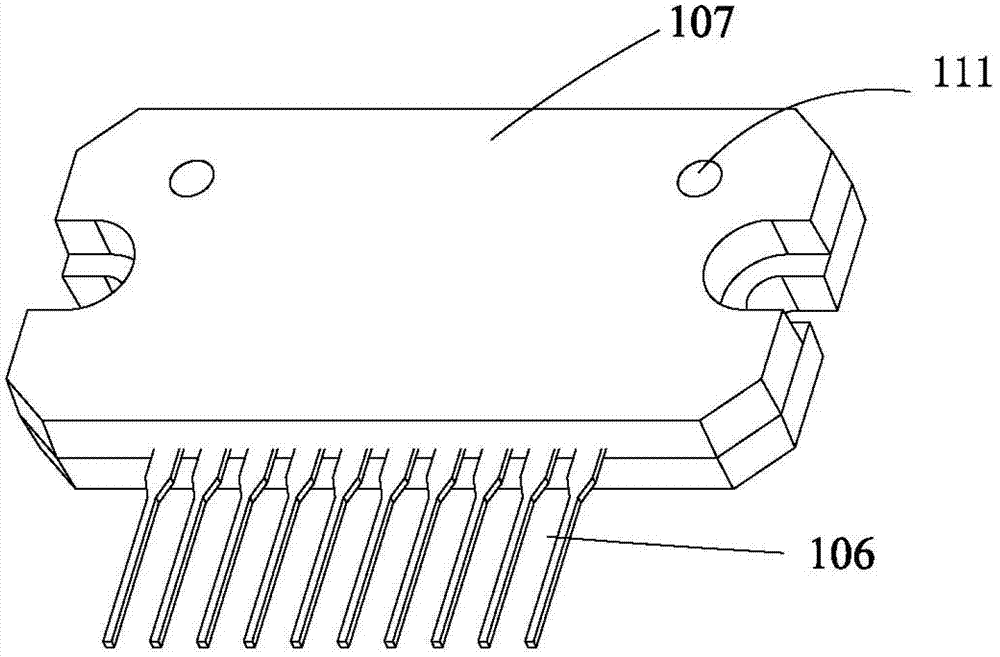
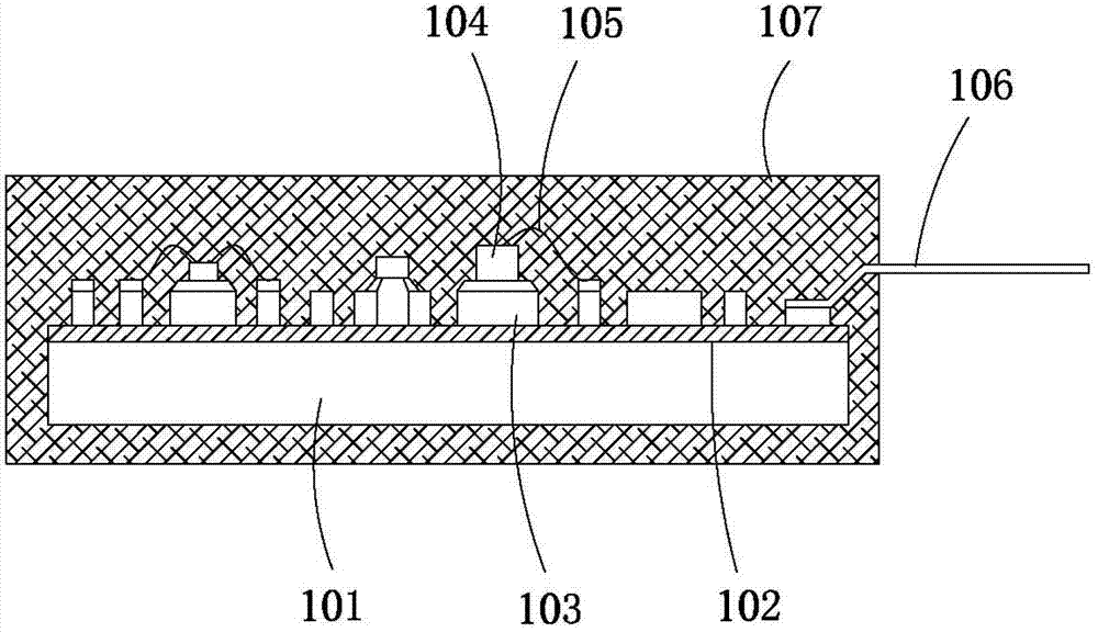
[0005] However, when using this method for positioning, due to the existence of the hole 111, it will inevitably affect the compactness of the smart power module package. The corroded gap between the substrates 101 enters the original sealed part of the circuit substrate 101. Once the water vapor touches the circuit wiring 103 or the circuit components 104, it will damage the circuit wiring and circuit components. failure, resulting in damage to equipment using intelligent power modules
[0006] In addition, this method of observing the packaging position of the circuit substrate 101 through the hole 111 is difficult to observe and measure the height due to the small diameter of the hole 111 and the position of the hole is in the middle of the sealing resin, and generally requires the use of expensive instruments such as optical detection equipment to determine , which increases the manufacturing cost and processing difficulty of the intelligent power module

Method used


Image

  • Intelligent power module manufacturing method and intelligent power module
  • Intelligent power module manufacturing method and intelligent power module
  • Intelligent power module manufacturing method and intelligent power module

Examples


Embodiment Construction

[0030] In order to make the objectives, technical solutions, and advantages of the present invention clearer, the following further describes the present invention in detail with reference to the accompanying drawings and embodiments. It should be understood that the specific embodiments described here are only used to explain the present invention, but not to limit the present invention.

[0031] The specific implementation of the present invention will be described in detail below in conjunction with specific embodiments:

[0032] Figure 4 Shows a flow chart of a method for manufacturing a smart power module provided by an embodiment of the present invention. FIG. 5 shows a structural diagram corresponding to each step in the method. For ease of description, only the parts related to this embodiment are shown. .

[0033] reference Figure 4 5. The method includes the following steps:

[0034] In step S101, a metal substrate 11 is selected, the insulating layer 12 and the circuit w...


PUM


Abstract

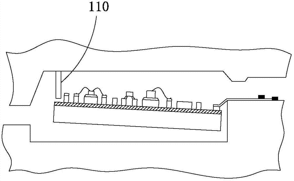
The invention is applicable to the technical field of electronic devices and provides an intelligent power module manufacturing method. The method comprises the following steps: selecting a metal substrate, arranging an insulating layer and a circuit wiring on the metal substrate, installing circuit elements and pins on the circuit wiring and enabling the run of the pins to gradually incline upward; placing the metal substrate in a packaging mold, fixing the pins on a horizontal plane through a first fixing device and making the surface of the metal substrate incline relative to the horizontal plane; configuring a metal pressing block parallel to the horizontal plane and pressing the metal pressing block on the metal substrate to make the metal pressing block parallel to the horizontal plane; and injecting packaging material in the mold to seal the substrate. The metal substrate is accurately positioned in the packaging mold through the metal pressing block, holes can be prevented from being reserved in the packaging structure, and the packaging compactness is improved. After packaging is completed, the position of the metal pressing block in the packaging structure can be directly measured by using a simple measuring tool so that the position of the metal substrate in the packaging mold can be known and subsequent inspection is facilitated.

Description

Technical field [0001] The invention belongs to the technical field of electronic devices, and particularly relates to a manufacturing method of an intelligent power module and an intelligent power module. Background technique [0002] Intelligent Power Module (Intelligent Power Module, IPM) is a power drive product that combines power electronics and integrated circuit technology. IPM integrates power switching devices and high-voltage drive circuits, and has built-in fault detection circuits such as overvoltage, overcurrent, and overheating. On the one hand, the IPM receives the control signal of the MCU and drives the subsequent circuit to work, on the other hand, it sends the state detection signal of the system back to the MCU. Compared with traditional discrete solutions, IPM has won an increasingly large market with its advantages of high integration and high reliability. It is especially suitable for frequency converters and various inverter power supplies for driving mo...

Claims


Application Information

Patent Timeline
Patent Type & Authority Applications(China)
IPC IPC(8): H01L21/56H01L25/16
CPCH01L2224/48091H01L2924/19105H01L2924/00014H01L21/565H01L21/56
Inventor 冯宇翔黄祥钧
Owner 美垦半导体技术有限公司
Why Eureka
Try Eureka