
Compact type glass structure medium-power carbon dioxide laser

A technology of carbon dioxide and lasers, which is applied in the field of lasers, can solve the problems of difficult configuration and the inability to use full transmission output windows for lasers, and achieve the effects of easy alignment, easy alignment adjustment, and simplified structure

Inactive Publication Date: 2014-04-09
丁健君
View PDF6 Cites 0 Cited by
  • Summary
  • Abstract
  • Description
  • Claims
  • Application Information

AI Technical Summary

Problems solved by technology

[0005] The present invention aims at the above-mentioned deficiencies existing in the prior art, and provides a compact glass-structure medium-power carbon dioxide laser, which overcomes the difficulty in configuring a large-diameter discharge tube in the prior art that the diameter of the output window must be the same as that of the rear full reflection mirror to increase the mode volume. And the disadvantages of output power, and then solve the feasibility of using a large diameter discharge tube and a small diameter output aperture to obtain a large power output of hundreds of watts; at the same time, it also solves the problem that this type of laser cannot use a full transmission output window

Method used


Image

  • Compact type glass structure medium-power carbon dioxide laser
  • Compact type glass structure medium-power carbon dioxide laser

Examples


Embodiment 1

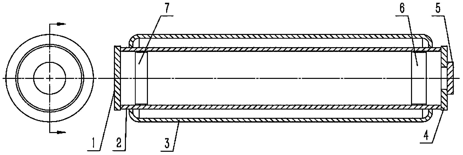
[0024] Such as figure 1 As shown, this embodiment includes: a first reflector 1 , a discharge tube 2 , a water cooling jacket 3 , a second reflector 4 , a transmissive output window 5 , a first electrode 6 and a second electrode 7 .

[0025] The first reflector 1 is an infrared total reflection concave mirror, the second reflector 4 is an infrared total reflection plane mirror with a hole in the center, and the transmissive output window 5 is an optical lens that can pass through infrared. The transmissive output window 5 is packaged in on the second reflector 4. The length of the discharge tube 2 is 1600 mm.

[0026] The shape of the first reflecting mirror 1 is circular, its diameter is 40 mm, and its thickness is 8 mm.

[0027] The shape of the second reflecting mirror 4 is circular, with an outer diameter of 40 mm, an inner diameter of 6 mm, and a thickness of 8 mm.

[0028] The central portion of the second reflecting mirror 4 is a circular hole, and the transmissive o...

Embodiment 2

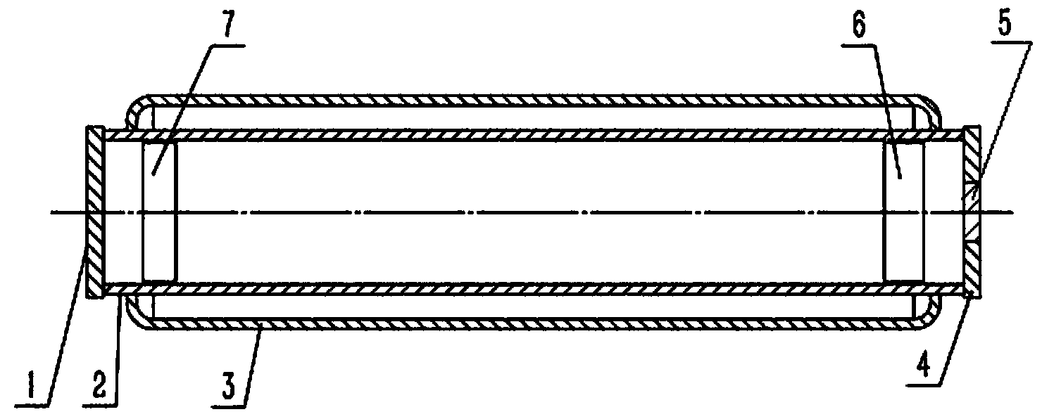
[0036] Such as figure 2 As shown, the basic structure and working principle of this embodiment are the same as those of Embodiment 1.

[0037] The first reflector 1 is an infrared total reflection concave mirror with a diameter of 45mm and a thickness of 8mm, but the second reflector and the transmissive output window 5 at its center are made of the same infrared transmission material (zinc selenide) The comprehensive function of reflection and transmission is realized by coating, that is, the annular inner surface of the transmission material is a total reflection surface, and the central circle part of the material is a transmission output window; the outer diameter of the second reflection mirror 4 is 45mm, 8mm in thickness, and 6mm in diameter of the laser output window in the central circle.

[0038] Compared with Embodiment 1, under the condition that the length of the discharge tube 2 is the same, since the diameter of the resonant cavity sheet at both ends in this embo...


PUM


Abstract

The invention belongs to the field of lasers and relates to a compact type glass structure carbon dioxide laser which comprises a first reflector, a discharging tube with the inner portion filled with carbon dioxide laser dielectric gas, a water cooling sleeve, a second reflector, an output window, a first electrode and a second electrode. The discharging tube is made of glass or quartz or ceramic. The first reflector and the second reflector are arranged at the two ends of the discharging tube respectively. The first reflector and the second reflector are total reflectors. A hole for laser to be output from is formed in the center of the second reflector at a laser output end. The transmission-type output window is arranged at the hole. The first electrode and the second electrode are arranged at the two ends of the discharging tube respectively. The water cooling sleeve is arranged on the outer portion of the discharging tube. The laser is compact in overall structure, and using value is improved.

Description

technical field [0001] The invention relates to a device in the field of lasers, in particular to a carbon dioxide laser with a compact glass structure and a power level of several hundred watts. Background technique [0002] The output power of existing glass-structured carbon dioxide lasers is generally around 100 watts. In order to achieve a medium power output of hundreds of watts, the length of the discharge tube is increased, that is, the effective discharge gas volume (mode volume) is increased to obtain a large laser. Output power, but it has its inherent shortcomings, such as the length of the discharge tube is increased and folded, and the compactness of the laser is not ideal in terms of structure. At the same time, because the output window is a half mirror, its diameter must be the same as that of the end reflector, so it is difficult to control the diameter of the output beam to a smaller size, so it is difficult to obtain hundreds of watts of power output and ...

Claims


Application Information

Patent Timeline
Patent Type & Authority Applications(China)
IPC IPC(8): H01S3/08
Inventor 丁健君
Owner 丁健君
Learn More