
Signal dither system and method based on switching period changes

A switching cycle and signal technology, applied in the field of signal processing, can solve the problems of introducing jitter ripple, large amount, etc., and achieve the effect of improving resolution, optimizing control effect, and increasing resolution

Inactive Publication Date: 2014-04-16
SUZHOU YINENG MICROELECTRONICS TECH
View PDF4 Cites 4 Cited by
  • Summary
  • Abstract
  • Description
  • Claims
  • Application Information

AI Technical Summary

Problems solved by technology

The use of signal dithering (Dither) technology is becoming wider and wider, and the beneficial effects brought by it have attracted more and more attention. However, the signal dithering (Dither) technology in current digital signal processing is based on the least significant bit (LSB) of the signal. Average the duty cycle of several adjacent switching cycles of the signal to obtain the average value to improve the accuracy of the control signal duty cycle. This method requires a large number of additional circuits, and the digital averaging method is inevitable Introduce jitter ripple

Method used


Image

  • Signal dither system and method based on switching period changes

Examples


Embodiment Construction

[0020] The present invention will be further described below in conjunction with the drawings.

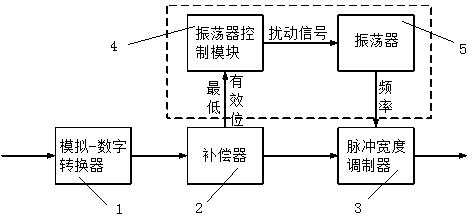
[0021] Such as figure 1 As shown, the signal jitter system based on the change of the switching cycle includes a DC-DC switching power supply circuit and a signal jitter circuit. The DC-DC switching power supply circuit includes an analog-digital converter 1, a compensator 2, and a pulse width modulator 3. -The digital converter 1 is connected to the pulse width modulator 3 via the compensator 2. According to the control principle, in order to avoid the generation of limit cycle oscillation, under the same bit width, the resolution of the pulse width modulator 3 must be greater than that of the analog-digital converter 1, which requires the use of higher resolution pulses Width modulator. Since the resolution of the pulse width modulator is closely related to the clock, the resolution of the pulse width modulator is directly proportional to the size of the clock. The resolution of t...


PUM


Abstract

The invention discloses a signal dither system and method based on switching period changes. The signal dither system comprises a signal dither circuit. When a DC-DC switching power circuit is connected with the signal dither circuit, the input end of an oscillator control module in the signal dither circuit is connected with the output end of a compensator in the DC-DC switching power circuit, the output end of an oscillator in the signal dither circuit is connected with the input end of a pulse width modulator in the DC-DC switching power circuit, a noise signal is added to the oscillator control module by judging the infinitesimal disturbance of the least significant bit of an output signal of the compensator in the switching frequency, a disturbance voltage is generated, switching frequency is generated by the oscillator according to the disturbance voltage, dither of the signal is achieved, the resolution ratio of the signal is obviously improved, the low-resolution-ratio pulse width modulator can be applied to the DC-DC switching power circuit, chip area can be effectively reduced, the signal resolution ratio can be obviously improved, and good application prospects can be achieved.

Description

Technical field [0001] The present invention relates to the field of signal processing, in particular to a signal dithering system and method based on switching cycle changes. Background technique [0002] Signal jitter (Dither) technology has been applied in many aspects, such as the use of dither in the control system for adaptive compensation of radar antennas; the use of dither in digital audio and video signals to reduce quantization effects; the image processing system uses dither (Dither) ) Signal, make the analog-digital converter (ADC) with 3~4 bit resolution display a good image with 6~7 bit resolution accuracy. Signal dithering (Dither) technology is used more and more widely, and its beneficial effects are getting more and more attention. However, the current signal dithering (Dither) technology in digital signal processing uses the least significant bit (LSB) of the signal. The duty cycle of several adjacent switching cycles of the signal is averaged to obtain the a...

Claims


Application Information

Patent Timeline
IPC IPC(8): H02M3/00H02M1/08
Inventor 吴钰淳
Owner SUZHOU YINENG MICROELECTRONICS TECH
Learn More