Unlock instant, AI-driven research and patent intelligence for your innovation.

Current zero-crossing detection circuit and method, driving circuit and method, switching power supply

A technology of zero-crossing detection and switching power supply, applied in the direction of measuring current/voltage, measuring devices, electrical components, etc., can solve the problems that are not suitable for the development trend of small size and low cost, increasing the size and cost of the driving circuit, etc.

Active Publication Date: 2017-05-31
BCD (SHANGHAI) MICRO ELECTRONICS LTD
View PDF10 Cites 0 Cited by
  • Summary
  • Abstract
  • Description
  • Claims
  • Application Information

AI Technical Summary

Problems solved by technology

[0004] However, the above-mentioned auxiliary winding will increase the size and cost of the drive circuit, which is not suitable for the current market trend of small size and low cost of LEDs.

Method used


Image

  • Current zero-crossing detection circuit and method, driving circuit and method, switching power supply
  • Current zero-crossing detection circuit and method, driving circuit and method, switching power supply
  • Current zero-crossing detection circuit and method, driving circuit and method, switching power supply

Examples


Embodiment 1

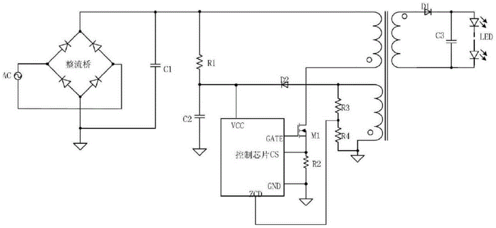
[0045] see figure 2 , is a structural schematic diagram of a driving circuit composed of a current zero-crossing detection circuit provided by the present invention, and the current zero-crossing detection circuit is applied to a switching power supply. Wherein, the switching power supply includes: a rectifier bridge DB1 , a first power switching tube M1 , a second power switching tube M2 and a switch control circuit 104 .

[0046] The current zero-crossing detection circuit is connected in series between the source of the first power switch tube M1 and the input terminal of the switch control circuit 104, and is used to detect the falling slope of the source voltage of the first power switch tube, and convert the falling slope to In order to compare the first voltage with the preset voltage, a secondary diode current zero-crossing signal is output to the switch control circuit to control the turn-on or turn-off of the second power switch tube.

[0047] from figure 2 It is...

Embodiment 2

[0064] On the basis of the first embodiment above, this embodiment further provides a drive circuit, including: a rectifier bridge, a first power switch tube, a second power switch tube, a switch control circuit, and the above-mentioned current zero-crossing detection circuit.

[0065] Wherein, the output end of the rectifier bridge is grounded through the first power switch tube and the second power switch tube connected in series. The current zero-crossing detection circuit is connected in series between the source of the first power switch tube and the input terminal of the switch control circuit. The output end of the switch control circuit is connected with the grid of the second power switch tube, and the control end of the switch control circuit is connected with the source of the second power switch tube.

[0066] It should be noted here that the circuit structure and working principle of the current zero-crossing detection circuit in this embodiment are the same as th...

Embodiment 3

[0074] Above we have introduced a current zero-crossing detection circuit, now combined with the above circuit, this embodiment also provides a current zero-crossing current detection method, the method includes:

[0075] S101: Detect the falling slope of the source voltage of the first power switch tube;

[0076] S102: converting the falling slope into a first voltage;

[0077] S103: Comparing the magnitude of the first voltage with the preset voltage, and outputting a secondary diode current zero-crossing signal.

[0078] In addition, on the basis of the above driving circuit, a driving method is provided, which includes:

[0079] S101: Detect the falling slope of the source voltage of the first power switch tube;

[0080] S102: converting the falling slope into a first voltage;

[0081] S103: Comparing the magnitude of the first voltage with the preset voltage, and outputting a secondary diode current zero-crossing signal;

[0082] S104: Control the turn-on or turn-off ...


PUM


Abstract

The invention provides a current zero crossing point detection circuit which is applied to a switch power source. The switch power source comprises a rectifier bridge, a first power switch tube, a second power switch tube and a switch control circuit. The current zero crossing point detection circuit is connected between the source electrode of the first power switch tube and the input end of the switch control circuit in series and used for detecting the descending slope of source electrode voltage of the first power switch tube, converting the descending slope into first voltage, comparing the first voltage with preset voltage, output primary diode current zero crossing point signals to the switch control circuit, and controlling switching on or off of the second power switch tube. The current zero crossing point detection circuit not only can detect current zero crossing point information of a secondary diode, but also does not need an independent transformer auxiliary winding, and is small in occupied space and low in cost.

Description

technical field [0001] The invention relates to the field of light-emitting diodes (LEDs), and more specifically, relates to a current zero-crossing detection circuit and method, a driving circuit and a method, and a switching power supply. Background technique [0002] figure 1 A simplified schematic diagram for a conventional flyback LED driver circuit, as figure 1 As shown, the alternating current is rectified by the rectifier bridge and then filtered by the capacitor C1 to generate a DC voltage, and then a low-voltage direct current is generated by the resistor R1 and the capacitor C2 to start the control chip, that is, to control the power switch M1 to turn on. The transformer of the drive circuit has three windings, wherein the primary winding is connected between the output terminal of the rectifier bridge and the drain of the power switch tube M1, the terminal of the secondary winding with the same name is connected to the anode of the secondary diode D1, and the au...

Claims


Application Information

Patent Timeline
Patent Type & Authority Patents(China)
IPC IPC(8): H02M7/217H02M3/335G01R19/175
Inventor 张炜周松明张铮栋刘准朱亚江
Owner BCD (SHANGHAI) MICRO ELECTRONICS LTD