Designing method for cutter used for drilling composite material component and cutter

A technology of composite material components and design methods, which is applied in the directions of drilling tool accessories, drilling/drilling equipment, and components of boring machines/drilling machines, etc., can solve problems such as easy delamination, and achieve the effect of improving processing efficiency

Active Publication Date: 2014-04-23
SHANGHAI AIRCRAFT MFG
View PDF7 Cites 17 Cited by
  • Summary
  • Abstract
  • Description
  • Claims
  • Application Information

AI Technical Summary

Problems solved by technology

[0008] The invention solves the technical problem that the composite material inside the composite material component is easy to delaminate during the drilling process

Method used


Image

  • Designing method for cutter used for drilling composite material component and cutter
  • Designing method for cutter used for drilling composite material component and cutter
  • Designing method for cutter used for drilling composite material component and cutter

Examples


Embodiment Construction

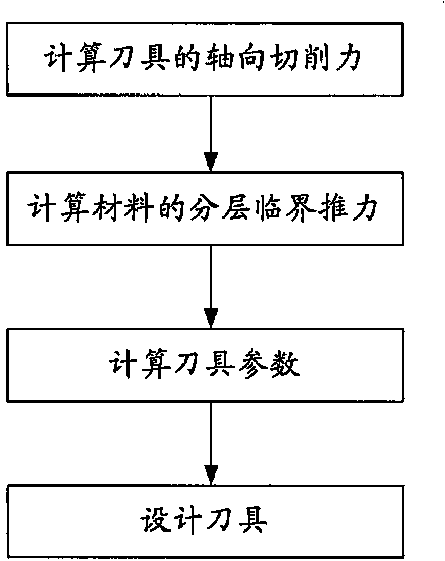
[0030]Step drill drilling tools can be considered as a combination of multi-stage drill bits. Here, such tools may include two-level drilling tools, three-level drilling tools, and further-level drilling tools. For two-stage drilling tools, there are upper-stage drills for drilling holes and lower-stage drills for reaming and larger diameters. For three-level drilling tools, it includes the uppermost drill bit for drilling and the smallest diameter, the lowest drill bit for reaming and the largest diameter, and the intermediate drill bit for reaming and the diameter between the first two , wherein the intermediate drill bit can be regarded as a lower-level drill bit for reaming, and can be regarded as a higher-level drill bit for reaming. For more levels of drilling tools, it includes the uppermost level drill bit for drilling and the smallest diameter, the lowest level drill bit for reaming and the largest diameter, and the role for reaming and the diameter is between the fo...


PUM


Abstract

The invention discloses a designing method for a drilling cutter. The cutter at least comprises an upper-grade drill bit with the preset diameter and a lower-grade drill bit with the diameter larger than the preset diameter. The method comprises the steps of calculating the axial drilling force of the cutter according to Fa=2A*10-1.089gamma(f / 2)0.5G1, calculating the material layering critical thrust according to (img file ='DDA0000433373030000011.TIF' wi='1347' he='207' / ) ( / maths), calculating the cutter parameters according to Fa<=FT, wherein the cutter parameters comprise the front angle gamma in the outer diameter of a main blade of the cutter, the top angle 2epsilon of the cutter, the width 2w of a transverse blade of the cutter and the diameters 2b and 2c of the cutter, and designing the cutter according to the cutter parameters obtained through calculation.

Description

technical field [0001] The invention relates to a method for designing a tool for drilling composite material components and a tool designed by the method, in particular to a method for machining holes in composite material components, especially carbon fiber reinforced composite material components, especially machining A design method for a tool with a large diameter hole and a tool designed by the method. Background technique [0002] Carbon fiber has very excellent mechanical properties and mechanical properties. Compared with other materials, it has higher specific strength and specific modulus. As a reinforcing material in composite materials, carbon fiber has the characteristics of high strength, high modulus and high brittleness. The matrix material has the characteristics of low strength, low modulus and good toughness. Most of the fighter jets that entered service in the world after the 1980s use carbon fiber composite materials for their wings and tail components...

Claims


Application Information

Patent Timeline
Patent Type & Authority Applications(China)
IPC IPC(8): B23B51/00
CPCB23B51/00
Inventor 蒋红宇陈明张烘州魏莹莹韩舒安庆龙刘登伟
Owner SHANGHAI AIRCRAFT MFG
Why Eureka
Try Eureka