Sealing valve discharge method and discharge device using same

A technology of valves and pressing devices, which is applied in the direction of transportation and packaging, conveyors, rotary conveyors, etc., can solve the problems of large particle material jamming, large particle material bridging, screw ash discharge valve leakage, etc., to achieve unloading Smooth ash, smooth nesting, and solve the stuck effect

Inactive Publication Date: 2014-04-23
喻成进
View PDF5 Cites 4 Cited by
  • Summary
  • Abstract
  • Description
  • Claims
  • Application Information

AI Technical Summary

Problems solved by technology

[0003] At present, the ash unloading valve mainly has the following three forms: the first one is the star ash unloading valve, which is mainly composed of a motor, a gear differential planetary reducer (or a needle cycloidal reducer) and a rotary dragon unloader. Relying on the gravity of the material and the coercive action of the working mechanism of the feeder, the material in the bin is unloaded and fed to the next device continuously and evenly. However, when the material is large and there are large particles, it is easy to get stuck Phenomenon, and there is air leakage, because the ash discharge port will generate a certain negative pressure, it is also easy to generate secondary dust, the cotton stripper of the condenser and the star ash discharge valve have the same working principle; the second is the ash discharge of the flap The valve, which uses the pressure of the material in the silo or ash hopper to open the valve plate, and after a certain amount of material is unloaded, the pressure on the valve plate decreases to automatically close. The discharged material has no thrust effect, and the large-grained material is prone to bridging and jamming, and secondary dust will also occur; the third type is the screw ash unloading valve, which also has air leakage and jamming. shortcoming

Method used


Image

  • Sealing valve discharge method and discharge device using same
  • Sealing valve discharge method and discharge device using same
  • Sealing valve discharge method and discharge device using same

Examples


Embodiment 1

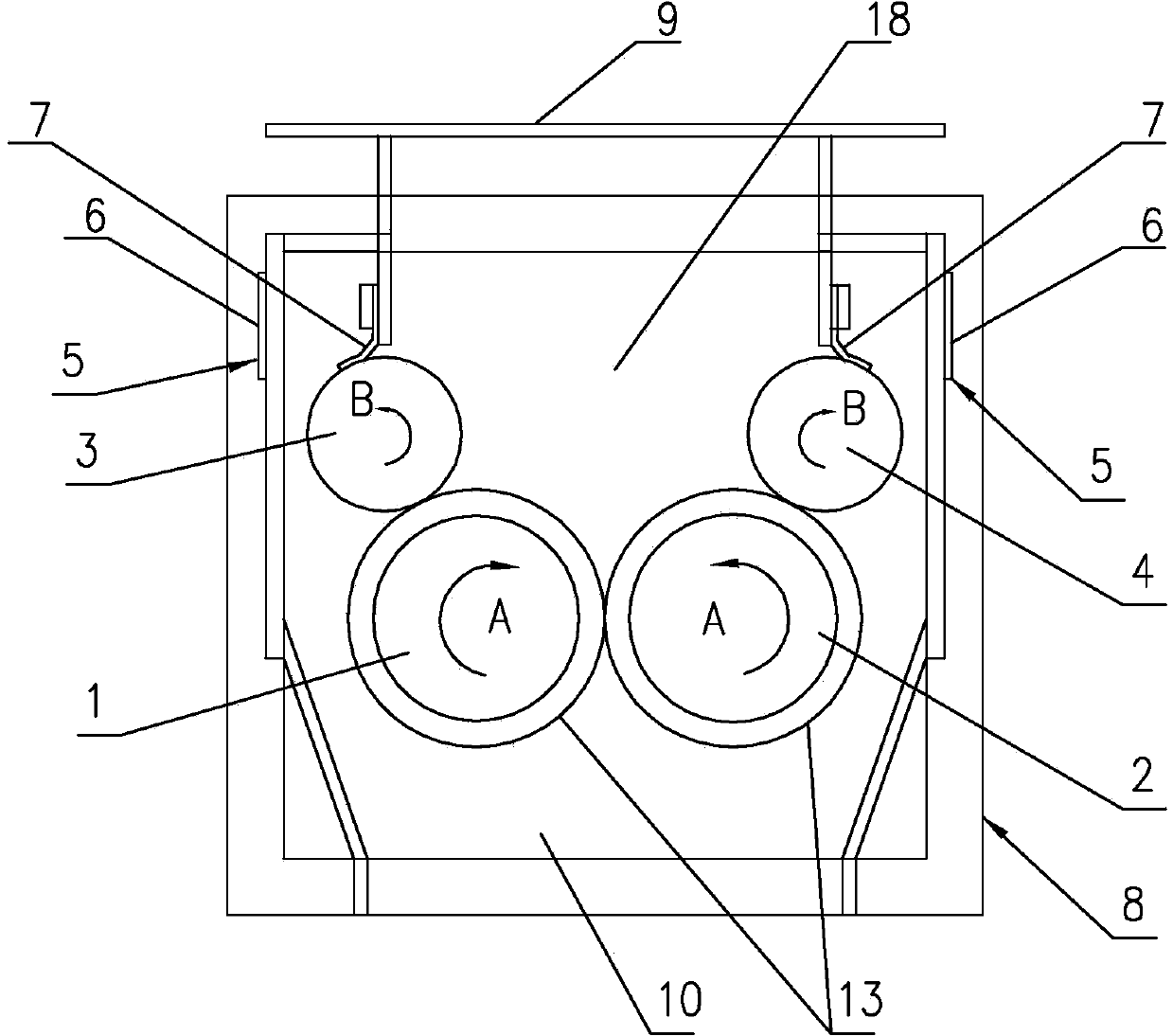
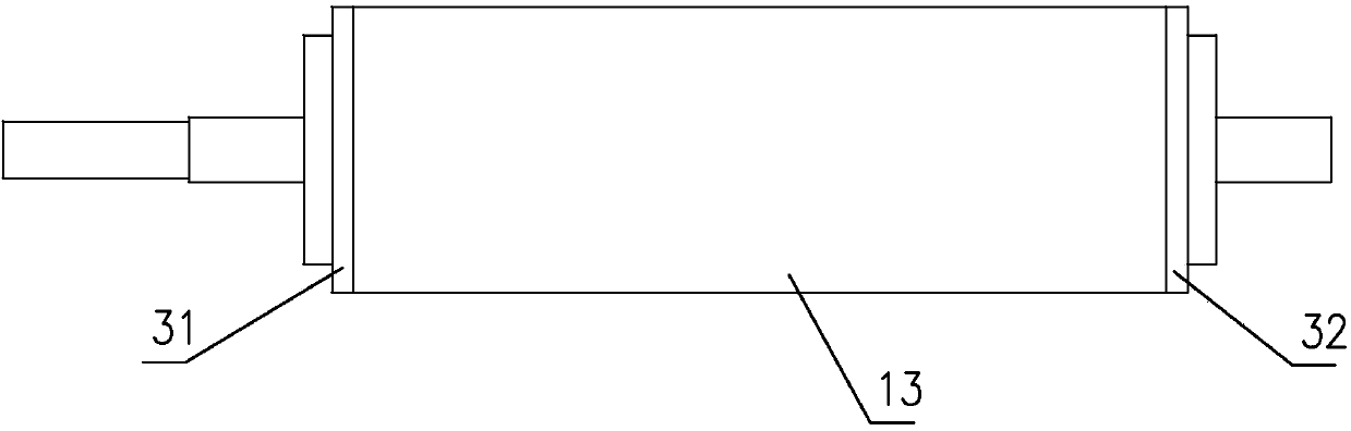
[0045] It is a sealing valve discharge method of the present invention. In an installation space, a pair of rollers arranged side by side, pressed against each other and capable of rotating inwardly in reverse are arranged. The rollers and the installation space form a closed space, and the outer wall of the rollers is wrapped Covered with elastic and wear-resistant lagging, the lagging on the two rollers is close to each other, and the material is squeezed out from the discharge space between the lagging on the two rollers, and the discharge space is squeezed by the elastic rubber on the roller. The lagging is formed by extrusion. When the material is squeezed by the elastic lagging on the two rollers, the lagging will release space for the material to be discharged under the action of elasticity. After the material is discharged, the lagging will remain in close contact under the action of elasticity to ensure no Air leak.

[0046] Such as Figure 1~3 As shown, it is a dis...

Embodiment 2

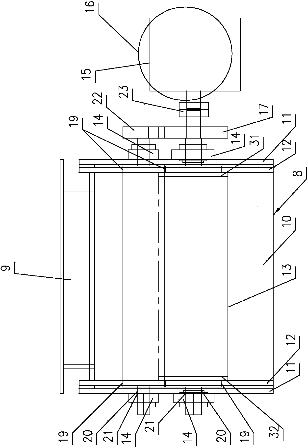
[0054] Such as Figure 4 , 5 As shown, the difference between this embodiment and Embodiment 1 is that a pair of pressing devices are installed on one of the closely attached rollers, and the material squeezes the rollers so that the rollers move outwards through the pressing devices to form a discharge space To ensure that the material is squeezed out from the discharge space. After the material is discharged, the pressing device will press the squeezed roller back to the tight state to ensure no air leakage. The pair of pressing devices are respectively arranged on both sides of the outer end of the outer plate of the casing. The pressing device includes two parallel support slide rails 41 fixed on the outer plate, and a T that is slidably installed on the two support slide rails. Type bearing 42, slide bar 43, spring pressing plate 41a and compression spring 44, and spring pressing plate 41a is fixed on the end of support slide rail 41, and the axle head of wherein a cyli...

Embodiment 3

[0056] The difference between this embodiment and Embodiment 2 is that no lagging is provided on the drum, and the discharge space is only formed by the space released by the material pressing the drum to move the drum outward. Specifically, it is realized by the pressing device in Embodiment 2, and the structure of the pressing device will not be repeated here.


PUM

PropertyMeasurementUnit
Thicknessaaaaaaaaaa
Thicknessaaaaaaaaaa
Thicknessaaaaaaaaaa

Abstract

The invention discloses a sealing valve discharge method. A pair of parallel, mutually compressed and reversely inward rotatable rollers are arranged in a mounting space, the rollers and the mounting space enclose a sealed space, and materials are squeezed out from discharge spaces of the rollers. The outer walls of the rollers are coated by elastic wear-resistant rubber coatings, the rubber coatings on the two rollers are clingy, the materials are squeezed out from the discharge spaces between the rubber coatings on the two rollers, a pair of compression devices are mounted on one of the rollers, and the materials squeeze the rollers to move outwards through the compression devices to form the discharge spaces, so that the materials can be squeezed out from the discharge spaces. The sealing valve discharge method is reliable in running, smooth in discharge, particularly applicable to textile industry and regenerated cotton industry and also applicable to the industry of discharged ash without massive hard objects, and sealing is ensured.

Description

technical field [0001] The invention belongs to the technical field of sealing valves and discharging equipment, and in particular relates to a sealing valve discharging method and a discharging device using the method, which is suitable for ash unloading valves and condenser discharging mechanisms. Background technique [0002] Sealed valve discharge is mainly used in the discharge mechanism of ash unloading valve and condenser. The dust discharge valve is an indispensable dust discharge device for dry dust collectors and material conveying systems. The dust collector collects the collected dust in the dust collection hopper of the dust collector, and then it is discharged by the dust discharge valve. The ash unloading valve is suitable for powdery and granular materials, and is widely used in environmental protection, metallurgy, chemical industry, grain, food and other industrial sectors. In order to ensure the normal operation of the dust collector, the dust discharge v...

Claims


Application Information

Patent Timeline
IPC IPC(8): B65G29/02
Inventor 吴广喻成进
Owner 喻成进
Why Eureka
Try Eureka