
Heat pump air-conditioning system for electric automobile

A technology for heat pump air conditioners and electric vehicles, which is applied in high-efficiency regulation technology, lighting and heating equipment, climate sustainability, etc., can solve the problems of unreliable performance, complex system design, and high cost, and achieve reliable performance, compact system structure, and high cost. low cost effect

Inactive Publication Date: 2014-04-23
ZHEJIANG CHUNHUI INTELLIGENT CONTROL
View PDF5 Cites 1 Cited by
  • Summary
  • Abstract
  • Description
  • Claims
  • Application Information

AI Technical Summary

Problems solved by technology

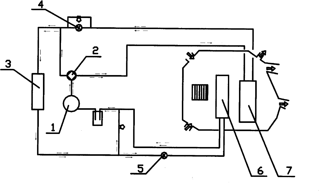
Although this system solves the two major problems of cooling and heating of the heat pump air conditioning system, it has disadvantages such as complex system design, high cost, and unreliable performance. In order to realize the two functions of cooling and heating of the heat pump air conditioning system, it is necessary to configure two electronic expansion valves , the cost is high. At the same time, as an actuator, the electronic expansion valve needs to be equipped with a controller and sensor that provides signals. Due to the complex and changeable environment of the car and the different driving habits of the driver, the algorithm of the controller is extremely complicated. The actual operating conditions of the air conditioner are difficult to completely match the design conditions, and the actual operating efficiency of the air conditioner is greatly reduced

Method used


Image

  • Heat pump air-conditioning system for electric automobile
  • Heat pump air-conditioning system for electric automobile

Examples


Embodiment Construction

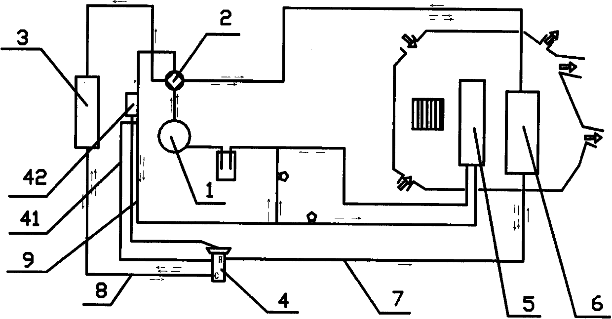
[0015] The present invention is mainly composed of a compressor 1, a four-way valve 2, an external heat exchanger 3, a two-way thermal expansion valve 4, an in-vehicle heat exchanger (A) 5, and an in-vehicle heat exchanger (B) 6. The expansion valve 4 is located between the external heat exchanger 3 and the internal heat exchanger (B) 6, the H interface of the two-way thermal expansion valve 4 is connected with the connecting pipe (A) 7, and the connecting pipe (A) 7 is connected with the vehicle The internal heat exchanger (B) 6 is connected, the C port of the two-way thermal expansion valve 4 is connected with the connecting pipe (B) 8, and the connecting pipe (B) 8 is connected with the external heat exchanger 3, and the two-way thermal expansion valve The outer balance pipe 41 communicates with the connecting pipe (C) 9 , and the temperature-sensing pipe 42 of the two-way thermal expansion valve contacts and binds with the connecting pipe (C) 9 .

[0016] It works as follo...


PUM


Abstract

The invention discloses a heat pump air-conditioning system for an electric automobile, and belongs to the technical field of compression type refrigeration. The heat pump air-conditioning system is applicable to various types of electric automobiles with heat pump air-conditioning systems. The heat pump air-conditioning system mainly comprises a compressor 1, a four-way valve 2, an external heat exchanger 3, a bidirectional thermostatic expansion valve 4, an internal heat exchanger (A) 5, an internal heat exchanger (B) 6 and the like, and is characterized in that the bidirectional thermostatic expansion valve 4 serves as a throttling element of the heat pump air-conditioning system for the electric automobile, and is positioned between the external heat exchanger 3 and the internal heat exchanger (B) 6. By using the bidirectional thermostatic expansion valve 4, the opening degree of a valve opening is automatically adjusted according to the degree of superheat of a collecting system, the refrigerant mass flow rate of a system is changed, the evaporation area of the system heat exchanger (which is the internal heat exchanger (B) 6 during refrigeration and is the external heat exchanger 3 during heating) is sufficiently utilized, and the system has the optimal efficacy. The heat pump air-conditioning system for the electric automobile has the advantages that the cost is low, the structure of the system is compact, the performance is reliable, and the like.

Description

technical field [0001] The invention relates to a heat pump air-conditioning system, which belongs to the technical field of vapor compression refrigeration and is suitable for various electric vehicles equipped with heat pump air-conditioning systems. Background technique [0002] The emergence of electric vehicles poses new issues and challenges to the research and development of electric vehicle air conditioners. Due to the uniqueness of electric vehicles, there is no engine as a power source for air-conditioning compressors, nor can it provide a heat source for automotive air-conditioning in winter. Domestic automobile manufacturers have carried out partial replacement designs on the basis of traditional fuel-fueled vehicle air-conditioners. The compressor driven by the engine is replaced by a compressor directly driven by a DC motor, and the control is changed accordingly to complete the cooling function of the air conditioner. The current replacement design effect can ...

Claims


Application Information

Patent Timeline
IPC IPC(8): F25B41/06F25B41/20F25B41/31
CPCY02B30/72Y02B30/70
Inventor 徐立中於君标王华达张斌叶志锋叶兴海丁炳华沈伟东
Owner ZHEJIANG CHUNHUI INTELLIGENT CONTROL
Learn More