Novel high-temperature and high-pressure electric heating furnace

A high-voltage electric and heating furnace technology, which is applied in the field of pyrolysis and combustion pilot-scale research, high-temperature and high-pressure electric heating furnaces, and the gasification of solid carbon-containing fuels under high-pressure and high-temperature conditions, which can solve the problem of inability to carry out pressure reaction and creep. , It is difficult to find problems such as high temperature and high pressure electric heating furnace to achieve the effect of continuous and stable high temperature and high pressure environment

Inactive Publication Date: 2014-04-23
SOUTHEAST UNIV
View PDF4 Cites 7 Cited by
  • Summary
  • Abstract
  • Description
  • Claims
  • Application Information

AI Technical Summary

Problems solved by technology

Common stainless steel pipes on the market can withstand pressure when used continuously at 800-1150°C, but when the temperature exceeds 1200°C, creeping phenomenon will occur and cannot withstand pressure
Therefore, if a stainless steel tube is used as the reaction tube, and the stainless steel tube is directly heated by electric heating, only normal pressure reaction can be carried out in the tube, and pressurized reaction cannot be carried out.
In view of the above reasons, the traditional heating furnace device is often difficult to meet both high pressure and high temperature conditions due to material limitations, and it is also difficult to find a high temperature and high pressure electric heating furnace that can react continuously on the market. Therefore, the high temperature and high temperature mentioned in the present invention Piezoelectric heating furnace has practical significance

Method used


Image

  • Novel high-temperature and high-pressure electric heating furnace
  • Novel high-temperature and high-pressure electric heating furnace
  • Novel high-temperature and high-pressure electric heating furnace

Examples


Embodiment Construction

[0019] In order to make the object, technical solution and advantages of the present invention clearer, the present invention will be further described in detail below in conjunction with the accompanying drawings and embodiments. It should be understood that the specific embodiments described here are only used to explain the present invention, not to limit the present invention.

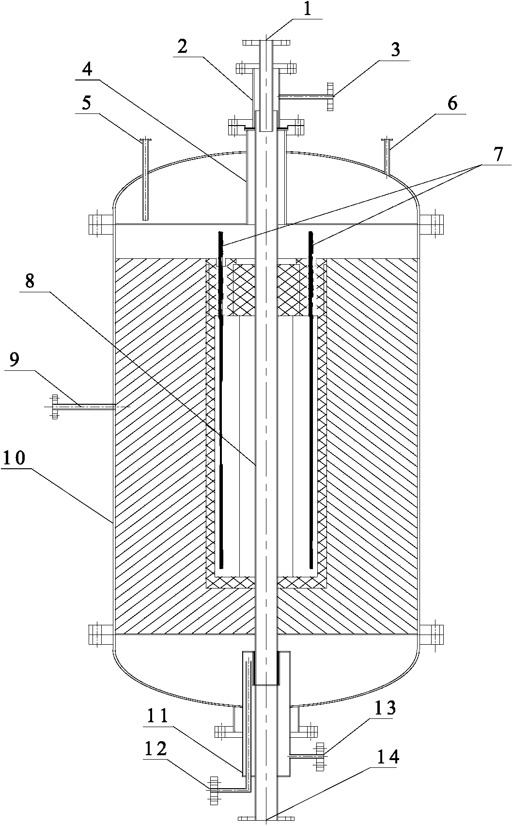
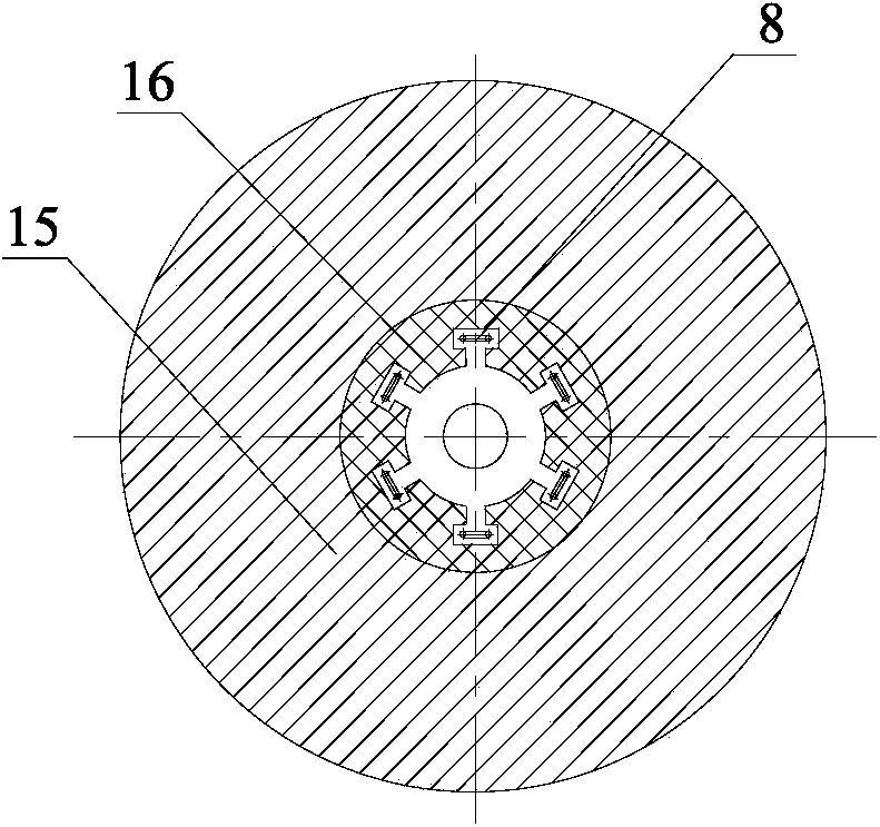
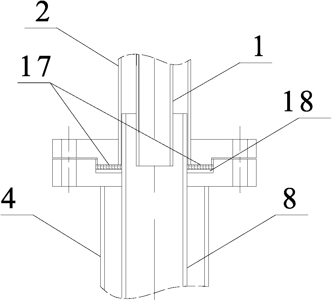
[0020] Such as figure 1 As shown, a new high-temperature and high-pressure electric heating furnace device includes a feeding pipe 1, a coupling 2, a reaction inlet pipe 3, an upper water cooling jacket 4, an upper cooling water inlet pipe 5, an upper cooling water outlet pipe 6, several silicon Molybdenum rod 7, Al 2 o 3 Ceramic reaction tube 8, lining inlet pipe 9, shell 10, lower water cooling jacket 11, lower cooling water inlet pipe 12, lower cooling water outlet pipe 13, slag discharge pipe 14, aluminum silicate fiber 15, zirconium-containing type 1400 ceramic fiber 16. Such as figure 2...


PUM


Abstract

A novel high-temperature and high-pressure electric heating furnace comprises a discharging tube, a reaction gas feeding tube, connectors, an Al2O3 ceramic reaction tube, a shell, a furnace lining gas feeding tube, silicon and molybdenum rods, aluminum silicate fiber heat-insulation cotton, a slagging tube and the like, wherein the upper end of the Al2O3 ceramic reaction tube is respectively connected with the discharging tube and the reaction gas feeding tube through the connectors, and connection positions are sealed by using graphite packing; the lower end of the Al2O3 ceramic reaction tube is connected with the slagging tube through a pipe, and a connection position is sealed by using high-temperature glue; the silicon and molybdenum rods are hung perpendicularly and are uniformly arranged around the Al2O3 ceramic reaction tube; a heat-insulation material is filled between the shell and an electric heating element; and inert gas with certain pressure is fed between the shell and the electric heating element. The Al2O3 ceramic reaction tube and the shell can bear the temperature of 1500 DEG C and the pressure of 1.5MPa, so that the novel high-temperature and high-pressure electric heating furnace is applicable to pilot-scale study on pyrolysis, gasification and combustion of solid carbonic fuels under the conditions of high temperature and high pressure, and has the advantages of quick temperature rising and stable pressurization.

Description

technical field [0001] The invention relates to a high-temperature and high-pressure electric heating furnace, which is especially suitable for pilot-scale research on the gasification, pyrolysis and combustion of solid carbon-containing fuels under high-pressure and high-temperature conditions, and belongs to the field of energy utilization. Background technique [0002] The high-temperature and high-pressure electric heating furnace not only has the characteristics of uniform furnace temperature and fast heat and mass transfer, but also increases the operating pressure of the heating furnace to make the equipment compact and reduce compression energy consumption and oxygen consumption. Temperature and pressure are key parameters that affect the rate of chemical reactions. For example, during coal pyrolysis, as the pressure increases, the formation rate of gaseous and solid products increases while the formation rate of liquid products decreases; as the temperature increases...

Claims


Application Information

Patent Timeline
Patent Type & Authority Applications(China)
IPC IPC(8): F27B17/02F27D11/02
Inventor 邵志伟黄亚继严玉朋刘长奇杨高强伏启让
Owner SOUTHEAST UNIV
Why Eureka
Try Eureka