Optical performance measurement method of a multifunctional lithium niobate integrated device

A technology of integrated devices and optical performance, applied in the direction of testing optical performance, etc., can solve the problems of being submerged in it, unable to obtain chip extinction ratio, difficulty, etc., and achieve the effect of reducing difficulty, simplifying the process of data analysis and processing, and easy to distinguish

Active Publication Date: 2017-02-22
HARBIN ENG UNIV
View PDF10 Cites 0 Cited by
  • Summary
  • Abstract
  • Description
  • Claims
  • Application Information

AI Technical Summary

Problems solved by technology

[0005] The Y waveguide is composed of three parts: input fiber, waveguide chip and output fiber. The traditional extinction ratio test is a lumped measurement, and only the overall extinction ratio value of the Y waveguide device can be obtained, that is, the sum of all extinction ratios of the device, and the waveguide chip The extinction ratio (50-80dB) is submerged in the extinction ratio (30-40dB) of the coupling between the fiber pigtail and the chip, and the extinction ratio of the chip cannot be obtained
Therefore, the main difficulties in measuring the extinction ratio of the Y waveguide device chip are: 1) The white light interferometer based on the principle of low coherence can realize the measurement of distributed polarization crosstalk, and can measure the parameters of the Y waveguide device (including the chip extinction ratio), but How to increase the resolution of polarization crosstalk to above -90dB, and realize the measurement of waveguide chips with an extinction ratio as high as 80dB or more; 2) In order to improve the spatial resolution, white light interferometers generally use SLD light sources with a wide spectrum, but the light source spectrum The ripple (ripple) will cause a coherence peak, and the corresponding polarization crosstalk amplitude is about -50 to -70dB. If the polarization crosstalk peak of the waveguide chip overlaps with it, the chip extinction ratio will be easily submerged in it. How to Eliminating its influence is a problem that needs to be solved urgently; 3) As a component of the waveguide device, it is quite difficult to accurately distinguish the crosstalk signals composed of chips, pigtails, etc. How to accurately identify white light interference signals is the difficulty of device testing one

Method used


Image

  • Optical performance measurement method of a multifunctional lithium niobate integrated device
  • Optical performance measurement method of a multifunctional lithium niobate integrated device
  • Optical performance measurement method of a multifunctional lithium niobate integrated device

Examples


Embodiment 1

[0096] Embodiment 1——Measurement of the Y-waveguide device with the slow axis of the pigtail and the fast axis of the waveguide chip

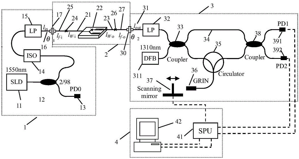
[0097] Device measurement devices such as figure 2 As shown, the device selection and parameters of the white light interferometry device are as follows:

[0098] (1) The central wavelength of the wide-spectrum light source 11 is 1550nm, the half-spectrum width is greater than 45nm, the fiber output power is greater than 2mW, the spectral ripple of the light source is <0.05dB (the peak amplitude is about -60dB), and the coherence peak range is 4-7mm; DFB light source The half-spectrum width of 311 is less than 50MHz, and the fiber output power is greater than 1mW;

[0099] (2) 2 / 98 fiber coupler 12 working wavelength 1550nm, splitting ratio 2:98;

[0100] (3) The optical fiber isolator 14 has an operating wavelength of 1550nm and an insertion loss of 0.8dB;

[0101] (4) The working wavelength of the white light interferometer output polariz...

Embodiment 2

[0124] Embodiment 2——Measurement of the Y waveguide device with the fast axis of the pigtail and the fast axis of the waveguide chip

[0125] The device measurement setup is also as figure 2 As shown, the selection and parameters of the measuring device are the same as in Example 1, except that the fast axis of the waveguide pigtail of the Y waveguide device to be tested is aligned with the fast axis of the waveguide chip, and the length of the waveguide chip is 30 mm.

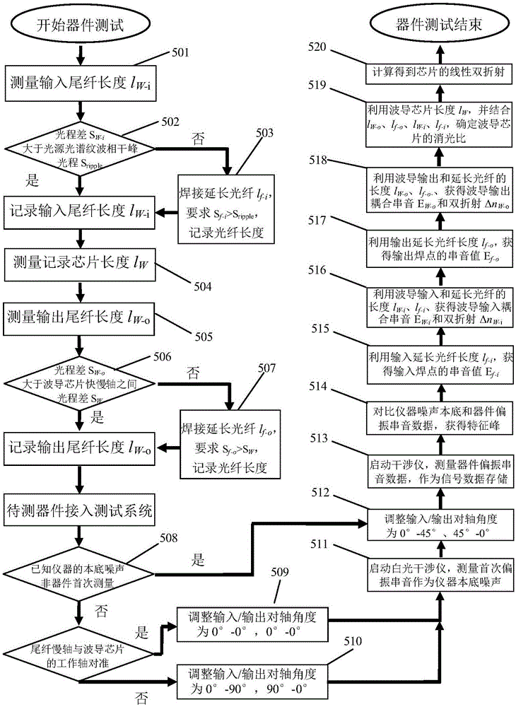
[0126] The specific process of device measurement is attached figure 1 Shown, its test process is roughly the same as embodiment 1, difference is:

[0127] (1) Measure the Y-waveguide input pigtail length l W-i = 6.11 meters, also need to connect the input extension fiber, take l f-i = 15.00 meters;

[0128] (2) Measure the output pigtail length l W-o is 0.90m, and the length of the waveguide chip is 30mm; it is also necessary to connect an extension fiber, take l f-o = 5.60 meters;

[0129] (3) Accord...


PUM

PropertyMeasurementUnit
lengthaaaaaaaaaa
lengthaaaaaaaaaa

Abstract

The invention belongs to the techical field of measurement of optical devices, in particular to a method for measuring optical performance of multi-functional lithium niobate integrator. The method includes the steps of: measuring a waveguide device inputting the length of a tail polarization-maintaining fiber; measuring the length waveguide chips; measuring the waveguide device outputting the length of a tail polarization-maintaining fiber; aiming at conveying axises of input / output a tail fiber slow axis and the waveguide chip; gaining the result of measuring a first distributed polarization crosstalk; changing the light injecting condition of the waveguide device; gaining the result of measuring a second distributed polarization crosstalk; through analyzing and calculating the data, gaining the optic parametric of the waveguide device. The method can not only exactly gain the extinction ratio of the waveguide chips and the linear birefringence, but also gain a coupling crosstalk and the linear birefringence of the chip waveguide fiber input / output end, an input / output extend fiber solder joint, and an optical defect inside of the waveguide chip and the connecting tail fiber, thereby decreasing the difficulty of reading and analyzing the signal, and simplifying the process of analyzing and managing the data.

Description

technical field [0001] The invention belongs to the technical field of optical device measurement, and in particular relates to a method for measuring the optical performance of a multifunctional lithium niobate integrated device. Background technique [0002] Multifunctional integrated optical devices are commonly known as "Y waveguides", generally using lithium niobate materials as the substrate, which highly integrates single-mode optical waveguides, optical beam splitters, optical modulators and optical polarizers, forming an interference fiber optic gyroscope The core components of (FOG) and fiber optic current transformer determine the measurement accuracy, stability, volume and cost of the fiber optic sensing system. [0003] The extinction ratio of the waveguide chip is an important parameter of the Y waveguide device. For example, for the Y waveguide used in the high-precision precision fiber optic gyroscope, the chip extinction ratio is required to be above 80dB. ...

Claims


Application Information

Patent Timeline
Patent Type & Authority Patents(China)
IPC IPC(8): G01M11/02
Inventor 杨军苑勇贵柴俊彭峰吴冰苑立波
Owner HARBIN ENG UNIV
Why Eureka
Try Eureka