Telescope secondary mirror position correcting method based on optical spot definition function

A correction method and definition technology, applied to telescopes, optics, optical components, etc., can solve problems such as system complexity, matrix relationship deviation, and increase the difficulty of engineering implementation, and achieve the effect of reducing system complexity and simple methods

Active Publication Date: 2014-04-23
INST OF OPTICS & ELECTRONICS - CHINESE ACAD OF SCI
View PDF3 Cites 15 Cited by
  • Summary
  • Abstract
  • Description
  • Claims
  • Application Information

AI Technical Summary

Problems solved by technology

The disadvantage of the first method is that the calculation complexity is high, and the correction result is greatly affected by the calculation accuracy.
The second method requires wavefront detectors, etc., which increases the complexity of the system
The matrix relationship established by the third method is an approximation when the error is small, and there is a large deviation in the matrix relationship when the error is large, and the acquisition of the aberration coefficient increases the complexity of the system
It can be seen from the published literature that the aberration correction method of the telescope system is mainly related to the wavefront aberration coefficient, which makes the system complex and increases the difficulty of engineering implementation

Method used


Image

  • Telescope secondary mirror position correcting method based on optical spot definition function
  • Telescope secondary mirror position correcting method based on optical spot definition function
  • Telescope secondary mirror position correcting method based on optical spot definition function

Examples


example

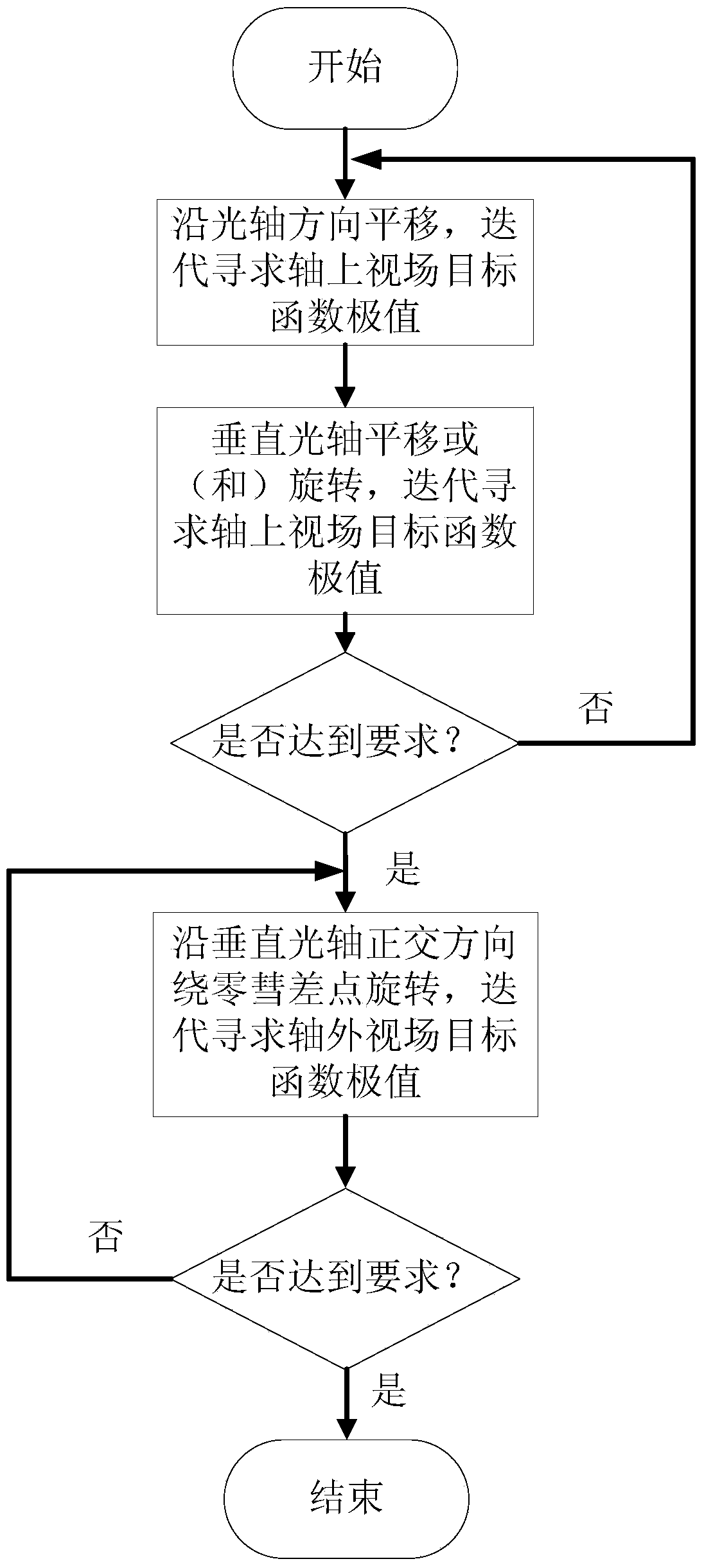
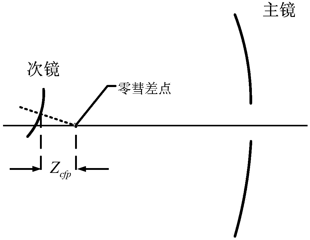
[0042] The simulation uses a two-mirror reflective RC optical system for correction simulation, and the system parameters are shown in Table 1. Put parameters into formula (3) to get Z cfp =-0.0106. The correction process was simulated by using ZEMAX optical design software and MATLAB programming software. The analysis process is carried out according to the steps in the correction process. Considering the existence of deviation, the astigmatism of the field of view on the axis is almost zero. The initial parameters of the correction are despace=80μm, decenterx=600μm, decentery=880μm, tiltx=0.02°, tilty=0.03°. The translation of the optical axis direction and the other four parameters all use the aforementioned stochastic parallel gradient descent algorithm (SPGD), so that the two are iterated separately. The objective function J gradually converges to the minimum value with iterations, such as Figure 5 Shown by the dotted line. The Strehl ratio of the on-axis field of vi...


PUM


Abstract

The invention discloses a telescope secondary mirror position correcting method based on optical spot definition function. The method comprises the following steps of 1, obtaining the position of a secondary mirror with objective function having an extreme value by taking onaxis field-of-view optical spot definition as the objective function, translation of the secondary mirror along the direction of an optical axis and translation and rotation of the secondary mirror along two orthogonal directions vertical to the optical axis direction through an iterative algorithm, wherein if all the variables are simultaneously iterated, the objective function is likely to be converged to a local extreme value, so that each iterative process is enabled to comprise two steps of iteration of the optical axis direction and the direction vertical to the optical axis direction so as to enable the objective function to be converged to a global extreme value; 2, enabling the secondary mirror to rotate around a zero comet difference point of a system along the two orthogonal directions and searching for the extreme value of the objective function in an iterative manner for realizing correction for the relative position of the secondary mirror by taking the mean value of definition function of multiple axis external field-of-view optical spots as the objective function. The method is free from wavefront detection and reestablishment, adjustment for a telescope system has an objective standard, and the telescope imaging quality can be monitored in real time.

Description

technical field [0001] The invention relates to a method for correcting the position of a secondary mirror of a telescope based on a light spot definition function. This method is suitable for the adjustment and online adjustment of the telescope system. Background technique [0002] Ideally, the relative positions of the primary and secondary mirrors of the telescope are fixed. However, due to the influence of temperature, gravity and other factors during operation, the relative positions of the primary and secondary mirrors will change. Taking the central vertex of the primary mirror as the origin of the reference coordinate system, the change of the system structure includes the translation of the secondary mirror along the optical axis, the translation in the vertical direction of the optical axis, and the rotation in the vertical direction of the optical axis. Changes in the relative positions of the primary and secondary mirrors will cause certain aberrations in the t...

Claims


Application Information

Patent Timeline
Patent Type & Authority Applications(China)
IPC IPC(8): G02B23/00
Inventor 鲜浩周龙峰张昂
Owner INST OF OPTICS & ELECTRONICS - CHINESE ACAD OF SCI
Why Eureka
Try Eureka