Sparking plug
A spark plug and spark discharge technology, applied in the field of spark plugs, can solve the problems of ignition time delay, increased distance, unfavorable energy saving and environmental protection, etc., and achieve the effects of improving ignition efficiency and return efficiency, improving utilization rate, and improving combustion efficiency
- Summary
- Abstract
- Description
- Claims
- Application Information
AI Technical Summary
Problems solved by technology
Method used
Image
Examples
Embodiment 1
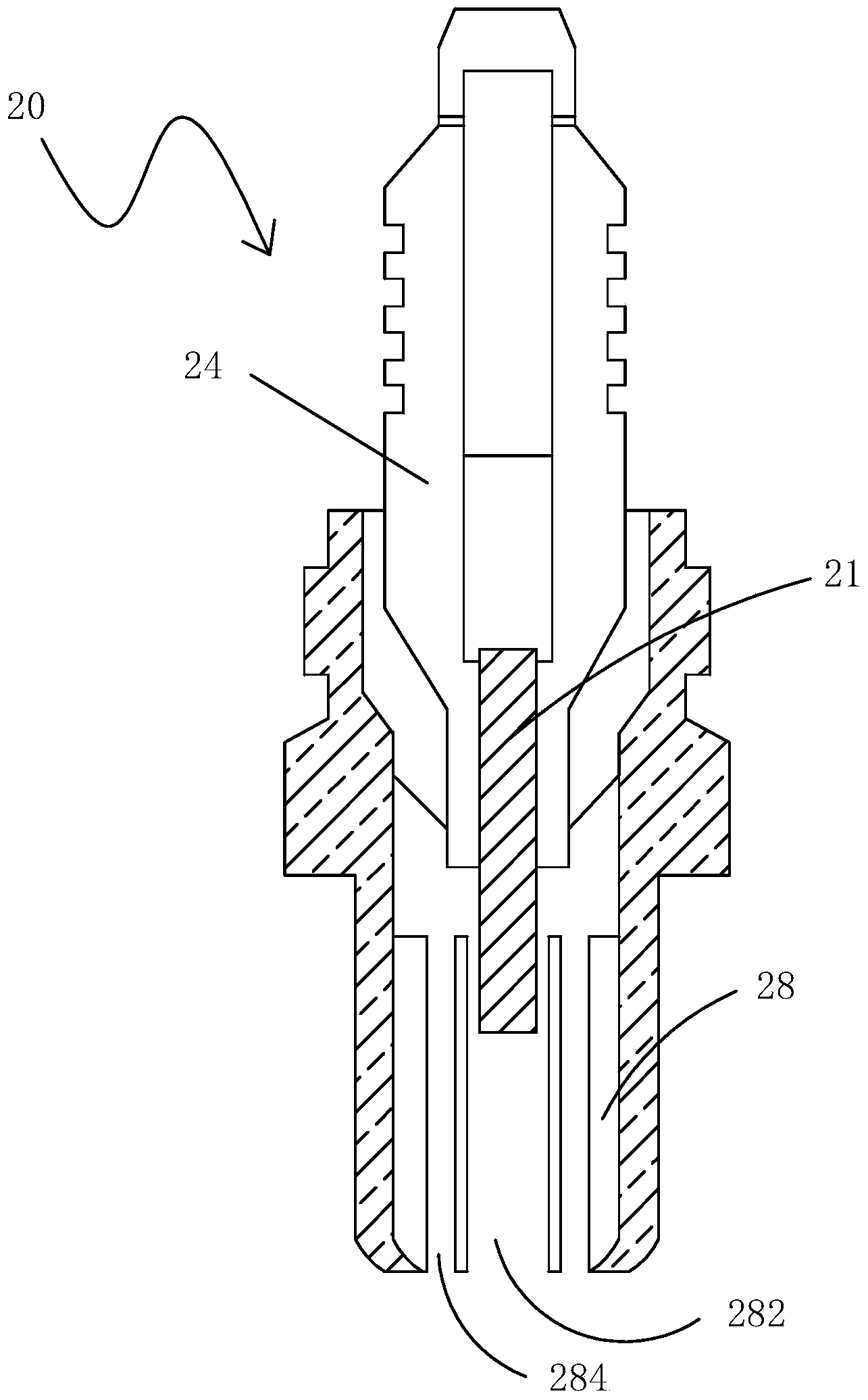
[0029] Please also see image 3 , which is a structural schematic diagram of Embodiment 1 of the spark plug of the present invention. The spark plug 20 includes a center electrode 21 , an insulator 24 , a housing 26 and a flow guiding insert 28 . The insulator 24 is a ceramic insulator, which has a shaft hole extending along the axial direction. The center electrode 21 is inserted through the shaft hole of the insulator 24 and exposes the end portion 211 . The housing 26 is hollow and sheathed on the surface of the insulator 24 . The flow guiding insert 28 is fixedly installed in the hollow housing 26 , its front end is facing the central electrode 21 , its rear end is located at the opening end of the housing 26 , and its outer wall is attached to the inner wall of the housing 26 .
[0030] Please also see Figure 4 ,actually image 3 Schematic diagram of the three-dimensional perspective structure of the flow guiding insert shown. The flow guide insert 28 is a columnar...
Embodiment 2
[0037] The spark plug of this embodiment 2 is substantially the same as that of embodiment 1, the only difference being that the structure of the guide insert of the spark plug is different. Please also see Figure 5 with Image 6 ,in, Figure 5 It is a structural schematic diagram of Embodiment 2 of the spark plug of the present invention. Image 6 It is a schematic structural diagram of the flow guide insert 38 of the second embodiment. The flow guide insert 38 is a columnar body, on which a flame injection hole 382 and a flow guide groove 383 are arranged. Wherein, the flame injection hole 382 is circular, located at the central axis of the flow guiding portion 38 , and runs through the front and rear end surfaces of the flow guiding portion 38 . The flow guide groove 383 is located on a sidewall of the flow guide portion 38 . The diversion groove 383 is formed by washing and cutting process, and the cross section can be formed into triangular, polygonal, arc and other...
Embodiment 3
[0040] The spark plug of the present embodiment 3 is substantially the same as that of the embodiment 1, and the only difference is that the structure of the guide insert of the spark plug is different. see Figure 7 , which is a schematic structural diagram of the flow guiding insert 48 of the third embodiment. The flow guide insert 48 is a columnar body, wherein the shaft is provided with a flame spray hole 482 that runs through the front and rear end surfaces of the flow guide insert 48 , and around the fire spray hole 482 is provided with a flow guide hole 483 that runs through the front and rear end surfaces of the flow guide insert 48 . The flow guide hole 483 communicates with the fire injection hole 482 through the inner cavity of the casing at the front end of the flow guide insert 48 . In the present embodiment, the aperture of the fire injection hole at the rear end of the flow guide insert is larger than the aperture at the front end, and the opening of the flame...
PUM
 Abstract
Description
Claims
Application Information
 - R&D
- Intellectual Property
- Life Sciences
- Materials
- Tech Scout
- Unparalleled Data Quality
- Higher Quality Content
- 60% Fewer Hallucinations
Browse by: Latest US Patents, China's latest patents, Technical Efficacy Thesaurus, Application Domain, Technology Topic, Popular Technical Reports.
© 2025 PatSnap. All rights reserved.Legal|Privacy policy|Modern Slavery Act Transparency Statement|Sitemap|About US| Contact US: help@patsnap.com


