
Flyback topology circuit with primary side control

A flyback topology, primary-side control technology, applied in the layout of electric lamp circuits, electric light sources, lighting devices, etc., can solve the problems of differential line adjustment rate and load adjustment rate, low precision, increasing chip development cycle and complexity, etc. Achieve the effect of reducing the difficulty of development and simplifying the circuit

Active Publication Date: 2015-07-29
SHANGHAI BRIGHT POWER SEMICONDUCTOR CO LTD
View PDF5 Cites 0 Cited by
  • Summary
  • Abstract
  • Description
  • Claims
  • Application Information

AI Technical Summary

Problems solved by technology

These different algorithms and circuits greatly increase the cycle and complexity of chip development. At the same time, some open-loop constant current algorithms also bring problems such as low precision, differential line adjustment rate and load regulation rate.

Method used


Image

  • Flyback topology circuit with primary side control
  • Flyback topology circuit with primary side control
  • Flyback topology circuit with primary side control

Examples


Embodiment

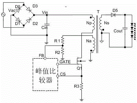
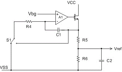
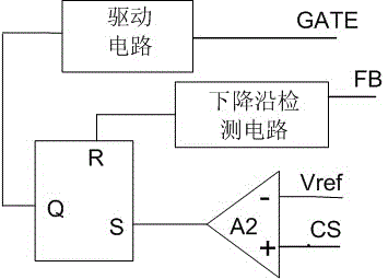
[0020] Such as figure 1 The shown flyback topology circuit using primary side control includes an integrating circuit, the integrating circuit is connected to the peak current comparator, the peak current comparator is connected to the inductance energy storage circuit, and the The inductance energy storage circuit is connected to the input end of the integrating circuit, the inductance energy storage circuit includes a bridge rectifier circuit and a transformer, the output end of the bridge rectifier circuit is connected to the first primary side Np of the transformer, the first The other end of the primary side Np is connected to the source of the N-type FET, one end of the second primary side Na of the transformer is grounded, and the other end is connected in series with a resistor R1 and a resistor R2, and the resistor R1 and the resistor The common end of R2 is connected to the peak current comparator, the gate and drain of the N-type field effect transistor are connecte...


PUM


Abstract

The invention discloses a flyback topology structure circuit employing primary side control. An integrating circuit is connected with a peak value current comparator; the peak value current comparator is connected with an inductor energy storage circuit; the output end of the bridge type rectification circuit of the inductor energy storage circuit is connected with a first primary side of a transformer; the other end of the first primary side is connected with the source electrode of an N type field effect transistor; one end of the second primary side of the transformer is grounded; the other end of the second primary side of the transformer is connected in series with a resistor R1 and a resistor R2; the common end of the resistor R1 and the resistor R2 is connected with the peak value current comparator; the gate electrode and the drain electrode of the N type field effect transistor are connected with the peak value comparator; the drain electrode of the N type field effect transistor is connected with the ground through a resistor R3; one end of the secondary side of the transformer is grounded, and the other end of the secondary side of the transformer is connected with the anode of a diode D5; and a capacitor is connected between the grounding end of the secondary side and the cathode of the diode D5. The advantages are as follows: the design of the circuit can be applied to internal integration of a chip and is free from periphery chip parameters, and development difficulty is lowered.

Description

technical field [0001] The invention relates to the field of semiconductor integrated circuits, and more specifically relates to a flyback topology circuit adopting primary side control. Background technique [0002] In recent years, due to the gradual improvement of the global awareness of green environmental protection, LED lighting products have been vigorously developed and gradually entered thousands of households. In LED lighting products, the AC-DC LED drive power supply circuit provides power for the LED, and because the LED (Light Emitting Diode) is a current device, the luminous brightness is greatly affected by the current, so the LED drive power supply needs to provide stable power for the LED. Constant current output. [0003] Currently, critical current conduction mode (BCM) and disconnection control mode (DCM) are widely used in LED lighting power drivers to achieve constant current output control. In order to achieve higher power efficiency, some power driv...

Claims


Application Information

Patent Timeline
Patent Type & Authority Patents(China)
IPC IPC(8): H05B37/02
Inventor 陈雪松易坤高继赵方麟
Owner SHANGHAI BRIGHT POWER SEMICONDUCTOR CO LTD
Learn More