Gas base permeation reactor

A gas-based infiltration and reactor technology, applied in the field of metallurgy, can solve problems such as unfavorable long-term development, increase cost investment, prolong operation time, etc., and achieve the effects of avoiding cumbersome and complicated, increasing effective contact area, and improving reaction rate

Inactive Publication Date: 2014-04-30
INNER MONGOLIA UNIV OF SCI & TECH
View PDF5 Cites 1 Cited by
  • Summary
  • Abstract
  • Description
  • Claims
  • Application Information

AI Technical Summary

Problems solved by technology

[0006] However, in the horizontal tube type rare earth concentrate powder reactor, when the gas reacts with the powder, a dense metal film will be formed on the surface of the rare earth concentrate powder, making it difficult for the reducing gas to enter the inside of the powder. In order to achieve the required The experimental effect must be achieved by prolonging the operating time and increasing the flow rate of the reducing gas
This will inevitably increase the cost of the experiment, and what is more serious is that the reaction rate is slow and the reduction rate is low, which affects the progress of the experiment.
[0007] To sum up, the process of producing rare earth metals by metallothermic reduction is cumbersome and the input cost is high; the reducing agent—coke—used in rare earth oxide agglomeration reduction method is increasingly in short supply, which is not conducive to long-term development; the existing horizontal tube type rare earth concentrate Although the powder reactor is in line with the future development of rare earth concentrate powder reduction research, its reaction rate is slow, which affects the experimental process, and needs to be improved to adapt to the rapid development of science and technology in today's world

Method used


Image

  • Gas base permeation reactor
  • Gas base permeation reactor

Examples


Embodiment Construction

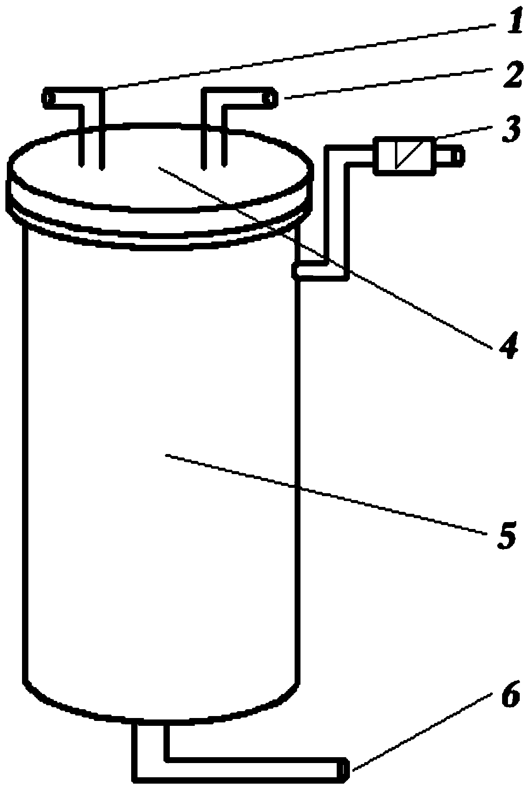
[0019] In Figure-1, the cooling water inlet 1 and the cooling water outlet 2 are welded on the reactor water-cooled furnace cover 4 and the reactor main body 5 is sealed and connected by bolts through gaskets, and the gas-based pressure stabilizing valve 3 is installed on the upper half of the reactor main body 5 part, it usually requires very stable working performance to ensure that the rare earth ore powder is not blown up by the variable pressure airflow, the reducing gas inlet 6 is welded at the bottom of the reactor main body 5, and the reducing gas (H 2 , CO, CH 4 ) from here.

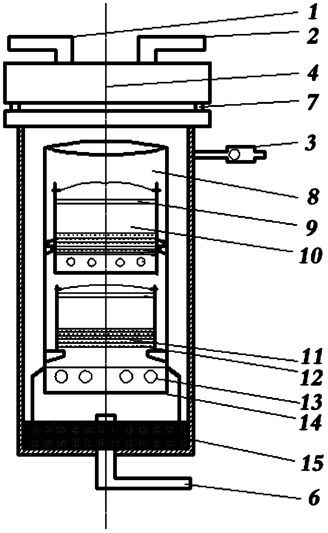
[0020] In the embodiment shown in Figure-2, all reactor components are made of steel, and the main body 5 of the gas-based permeation reactor is a cylinder with a volume of 1.9635L (diameter D is 10cm and height H is 25cm); the reactor The lower part of the main body 5 is provided with a sealing material 15, and the sealing material 15 is made of alumina powder. At least one small sleeve for r...


PUM


Abstract

The invention relates to a gas base permeation reactor, which belongs to the technical field of metallurgy. A cool water inlet and a cool water outlet are arranged on a water cooled cover of the reactor, a reducing gas inlet pipe is arranged on the bottom of a reactor main body, one end of the reducing gas inlet pipe extends into the bottom in the reactor main body, the bottom of the reactor main body is provided with a sealing material, the sealing material is connected with the bottom of a large loading sleeve, air inlet holes are formed in the lateral wall of the lower part of the large loading sleeve along the circumference direction, and at least one small sleeve for reducing mineral powder is arranged in the large loading sleeve. The reducing gas deeply permeates and enters into the rare earth concentrate powder in gaps of a multi-layer steel net, the effective contact area of the reducing gas and the rare earth concentrate powder is improved, the reaction rate is improved, and better experiment result can be completed at lower investment in very short time, so as to reach the unforeseen experiment purpose. Moreover, the complicated preparation process of rare earth metals by the metallothermic method is avoided, and the coke which is increasingly lacked and used in the rare earth oxides agglomeration reducing method is saved.

Description

technical field [0001] The invention relates to a gas-based permeation reactor, which belongs to the field of metallurgy. Background technique [0002] The term "rare earth" is a name that has been used since the eighteenth century, because the minerals used to extract such elements were relatively rare at that time, and the obtained oxides were difficult to melt, dissolve in water, and be difficult to separate. Soil" and called rare earths. Since the 19th century, the relatively mature method used to prepare rare earth metals is the preparation of rare earth metal by metallothermic reduction. The process of reducing rare earth compounds to metals with metal reducing agents with stronger activity than rare earths at high temperature. This is an important method for the production of rare earth metals, and the metal reducing agents used include calcium, lithium, lanthanum and cerium. The specific operation is to dissolve rare earth oxides that are insoluble in water in aci...

Claims


Application Information

Patent Timeline
Patent Type & Authority Applications(China)
IPC IPC(8): B01J8/02
Inventor 闫永旺范秀风陈义胜庞赟佶陈俊俊
Owner INNER MONGOLIA UNIV OF SCI & TECH
Why Eureka
Try Eureka