Method for machining rotor spindle of high pressure turbine

A technology of machining and high-pressure turbine, applied in the field of machining, can solve the problems of lengthy process, low pass rate of static balance superimposed projection detection, etc., and achieve the effect of ensuring shot peening strength and avoiding deformation.

Active Publication Date: 2014-04-30
西安西航集团莱特航空制造技术有限公司
View PDF5 Cites 4 Cited by
  • Summary
  • Abstract
  • Description
  • Claims
  • Application Information

AI Technical Summary

Problems solved by technology

There are 6 processes in lathe processing, the process is lengthy, and the method of processing and positioning reference each other leads to repeated duplication and superposition of the shape error of the inner and outer circles
Secondly, it is not possible to well control the deformation of the part due to the long distance between the cantilever arm and the positioning surface of the thin arm part, and the static balance required by the part design and the pass rate of superimposed projection detection are low.

Method used


Image

  • Method for machining rotor spindle of high pressure turbine
  • Method for machining rotor spindle of high pressure turbine
  • Method for machining rotor spindle of high pressure turbine

Examples


Embodiment Construction

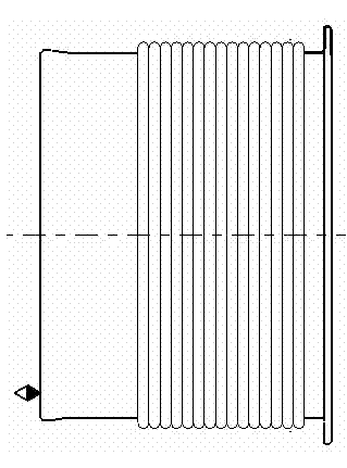
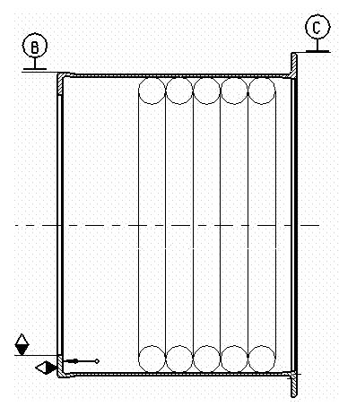
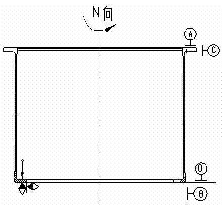
[0023] The processing route of the high-pressure turbine rotor shaft of the present invention: rear end positioning, semi-finishing front-end positioning, semi-finishing rear-rear positioning, finishing front-front positioning, finishing rear-processing end face, sector Groove - shot peening - finish turning seam - static balance - superimposed projection detection.

[0024] The rear end positioning described above, the front end of the semi-finishing car: the rough machining front adopts a ceramic knife with a large cutting capacity of 1.2mm-2mm, a high cutting speed of 180-208min / m and a large feed rate of 0.2-0.3mm / r to remove the allowance;

[0025] The front end positioning described above, the rear end of the semi-finishing car: the rough machining rear end also adopts ceramic knives with a large cutting amount of 1.2mm-2mm, a high cutting speed of 180-208min / m and a large feed rate of 0.2-0.3mm / r to remove excess quantity;

[0026] Directly carry out semi-finishing mac...


PUM

PropertyMeasurementUnit
surface smoothnessaaaaaaaaaa
Circularityaaaaaaaaaa

Abstract

The invention belongs to the technical field of machining and relates to a method for machining a rotor spindle of a high pressure turbine. Finish turning process is performed by using a rubber belt to wind parts, so that deformation of thin-walled workpieces is avoided. Spot facing machining tests cutting parameters, tool wear is controlled, and tool changing points are determined. Intensity check is performed on simulation test sheets through shot blasting so as to guarantee shot blasting intensity of the parts. The parts are subjected to static balance detection and superposition projection detection after processing. The method for machining the rotor spindle of the high pressure turbine includes the following steps of rear end positioning, front end half finish turning, front end positioning, rear end half finish turning, rear end positioning, front end finish turning, front end positioning, rear end finish turning, end face hole and fan-shaped groove machining, shot blasting, spigot finish turning, static balance detection, and superposition projection detection.

Description

technical field [0001] The invention belongs to the technical field of machining, and relates to a machining method for a high-pressure turbine rotor shaft. Background technique [0002] The high-pressure turbine rotor shaft is a key part of the aircraft engine. The material nickel-based superalloy (Inconel718) has high hardness, high strength, corrosion resistance, and high temperature resistance. [0003] The characteristics of parts processing are that the outer end of the part hangs out longer, the wall thickness is thinner and the variation of the circumferential wall thickness is strict, the material removal is more than 70%, and the cutting efficiency has a great impact on the production cycle and cost. There are 6 processes in the turning process, the process is lengthy, and the method of processing and positioning reference each other leads to repeated duplication and superposition of the shape errors of the inner and outer circles. Secondly, it is not possible to ...

Claims


Application Information

Patent Timeline
Patent Type & Authority Applications(China)
IPC IPC(8): B23P15/00
CPCB23P15/14B23P2700/01
Inventor 乔振华王乃翠吴江王东王斌
Owner 西安西航集团莱特航空制造技术有限公司
Why Eureka
Try Eureka