
Milling cutter eccentricity rapidly measured non-contact type laser measuring method

A laser measurement, non-contact technology, applied in the direction of measuring/indicating equipment, metal processing machinery parts, metal processing equipment, etc., can solve the problems of process system stiffness changes, bandwidth limitations, difficult to operate, etc., to achieve reasonable processing parameters, The effect of ensuring stability

Active Publication Date: 2014-04-30
WUXI TURBINE BLADE
View PDF4 Cites 23 Cited by
  • Summary
  • Abstract
  • Description
  • Claims
  • Application Information

AI Technical Summary

Problems solved by technology

However, the method of identifying tool eccentricity based on cutting force signals also has the following disadvantages: (1) The cutting force test must be equipped with an expensive dynamic cutting dynamometer; (2) It is difficult to operate in the actual environment of the factory production workshop; (3) Installation The stiffness of the process system after the dynamometer will change; (4) Due to the limitation of the bandwidth collected by the dynamometer (usually 2~3kHz), the cutting force signal will be distorted and deformed under high-speed rotation
[0004] Most of the existing precision CNC machine tools generally have a laser displacement sensor measurement function, but it can only give the maximum diameter of the actual cutting edge cutting in the case of tool eccentricity, but cannot give the specific tool eccentricity value

Method used

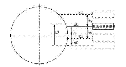
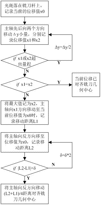
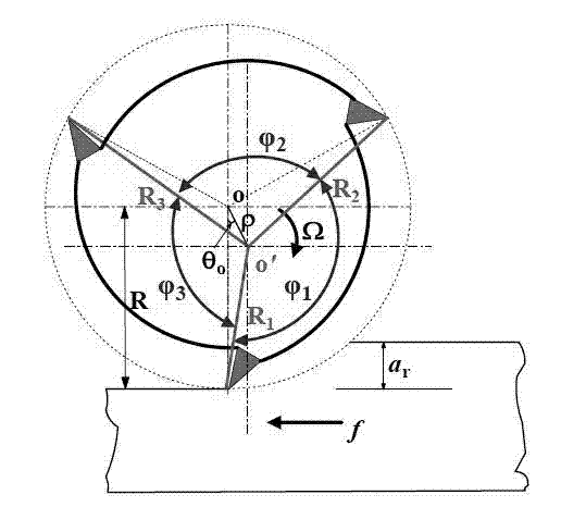

Image

  • Milling cutter eccentricity rapidly measured non-contact type laser measuring method
  • Milling cutter eccentricity rapidly measured non-contact type laser measuring method
  • Milling cutter eccentricity rapidly measured non-contact type laser measuring method

Examples


Embodiment Construction

[0032]The acceptance scheme of the present invention will be further described in detail below in conjunction with the accompanying drawings and examples: This example chooses a carbide three-tooth flat-bottomed end mill as a machining tool with a uniform pitch, and the tool is clamped on a Mikron ucp800 five-axis machine tool On the above, the geometric parameters of the tool are: the measured diameter is 7.99 mm (the nominal value is 8 mm); the helix angle is 30 degrees; the total length is 65 mm; the cantilever length is 35 mm. According to the method of the present invention, carry out the eccentricity test under the situation of milling cutter rotation, its steps are:

[0033] 1. A laser displacement sensor is installed on the machine tool, and the displacement sensor is connected to the collector and the industrial computer. The technical parameters of the laser displacement sensor measurement system used are: a laser spot with a diameter of 30 microns, a sampling frequen...


PUM


Abstract

The invention provides a milling cutter eccentricity rapidly measured non-contact type laser measuring method. The milling cutter eccentricity rapidly measured non-contact type laser measuring method can rapidly obtain the actual cutter eccentricity after a milling cutter is installed, accordingly whether the installation is reasonable or not is judged and efficient machining parameter is confirmed and part accurately and efficiently machining is achieved. The milling cutter eccentricity rapidly measured non-contact type laser measuring method is characterized in that dynamic displacement of the milling cutter during rotation at different rotating speed is collected through a laser displacement sensor; the peak-peak value of the dynamic displacement under different rotating speed through filtering waves are obtained; a mathematical model for solving the milling cutter eccentricity is constructed according to the peak-peak value; the actual milling cutter eccentricity is obtained due to solving of an optimizing model of the milling cutter eccentricity.

Description

technical field [0001] The invention relates to the technical field of on-line measurement of numerical control machining, in particular to a milling cutter eccentricity measurement method, in particular to a non-contact laser measurement method for quickly measuring milling cutter eccentricity. Background technique [0002] In the process of high-speed machining of machine tools, milling cutters often have misalignment between the center of rotation of the milling cutter and the geometric center of the tool due to problems such as installation and thermal expansion, that is, tool eccentricity occurs. The eccentricity of the uniformly distributed standard multi-tooth milling cutter will cause inconsistent cutting loads on each cutting edge of the milling cutter, resulting in inconsistent cutting forces on different cutting edges, resulting in rapid wear of the cutting edge and changes in the machined surface morphology. It is particularly important in processing. In the cur...

Claims


Application Information

Patent Timeline
Patent Type & Authority Applications(China)
IPC IPC(8): B23Q17/24B23Q17/22
CPCB23Q17/2428B23Q2017/001
Inventor 张小俭滕树新贺明张家军
Owner WUXI TURBINE BLADE
Learn More