Device and method for detecting double parts

一种复式、零件的技术,应用在用于探测复式零件和装置领域,达到改善工艺可靠性、可靠控制的效果

Active Publication Date: 2014-04-30
ROLAND ELECTRONICS
View PDF8 Cites 0 Cited by
  • Summary
  • Abstract
  • Description
  • Claims
  • Application Information

AI Technical Summary

Problems solved by technology

The known laser sensors show here the inherent disadvantage that they only show up when the laser beam fails
This can lead to material passing through the measuring gap unnoticed
This is particularly serious, since the composite panel control is practically no longer process-reliable at this time

Method used


Image

  • Device and method for detecting double parts

Examples


Embodiment Construction

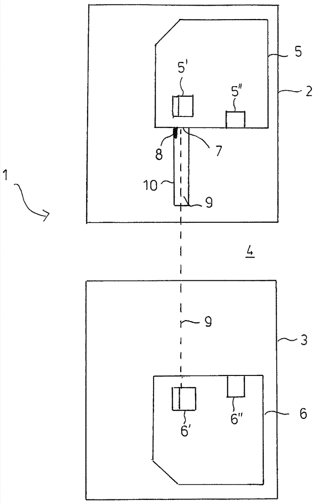
[0023] The drawing shows a device 1 with a first laser sensor unit 2 and a second laser sensor unit 3 . A measuring gap 4 is formed between the laser sensor units 2 , 3 . Each laser sensor unit 2 , 3 has a laser sensor 5 or 6 , which respectively contains a laser source 5 ′, 6 ′ and a detector 5 ″, 6 ″ for distance measurement in a known manner. The signal provided by the laser detector is evaluated by means of a control unit (not shown). On the laser sensor 5 there is a sleeve 10 for shielding from external light, which has a photoelectric receiver 8 on the inside at its end close to the exit window 7 of the laser sensor 5 . The photoreceiver 8 can be an ordinary photodiode. The photodiode detects light from a laser beam 9 originating from a laser source 6 ′ arranged in the laser sensor 6 as scattered light reflected back by the exit window 7 . The signal provided by the photodiode 8 is likewise fed to a not shown electrical control unit for evaluation.

[0024] The absen...


PUM


Abstract

The present invention relates to a device and a method for detecting double parts, and especially relates to an assembly of an additional photo receiver in addition to the known laser sensors for detecting double parts during transport and during the loading of machine, which are situated opposite each other. The additional photo receiver receives the laser beam from a laser sensor located opposite, exactly when there is no material in the measuring gap and the two laser sensors are precisely aligned. This arrangement makes it possible to improve the measuring process and the analysis of the measurement, and thereby increases process reliability during the monitoring of transport and the loading of machines.

Description

technical field [0001] The invention relates to a method for detecting duplex parts (Doppelteil) during transport and during feeding of a machine by means of two laser sensors arranged opposite each other, the laser sensors respectively having a laser source and a detector, the parts being processed by the laser travel between source and detector, wherein the distance between the respective laser sensor and the surface of the component facing the laser sensor is measured, and the distance between the laser sensors from one another and the distance measured by the two laser sensors The difference between the sums to find the thickness of the part. Furthermore, the invention relates to a device for detecting multiple parts during transport and when feeding a machine, with two laser sensor units arranged opposite each other and with which the laser sensor units are connected or can be connected. A connected electronic control unit, the laser sensor units are arranged at a distan...

Claims


Application Information

Patent Timeline
Patent Type & Authority Applications(China)
IPC IPC(8): B65H7/12G01B11/06
CPCB65H2511/524G01B11/0691B65H2511/22B65H2515/60B65H2553/412B65H2511/13B65H2511/51B65H7/125B65H7/04B65H2220/03B65H2220/01
Inventor F.瓦尔希M.阿明格翁J.曼茨
Owner ROLAND ELECTRONICS
Why Eureka
Try Eureka