Multistage water cushion rotational flow vertical shaft flood discharging tunnel suitable for high water head

A technology of high water head and flood discharge tunnel, which is applied in water conservancy engineering, marine engineering, coastline protection, etc., to avoid cavitation damage and improve energy dissipation rate.

Active Publication Date: 2014-04-30
SICHUAN UNIV
View PDF6 Cites 3 Cited by
  • Summary
  • Abstract
  • Description
  • Claims
  • Application Information

AI Technical Summary

Problems solved by technology

[0003] Aiming at the problems existing in the application of existing swirl shafts in high water head hydraulic projects, the purpose of the present invention is to provide a multi-stage water cushion swirl shaft flood discharge tunnel suitable for high water heads, so as to control the water flow velocity in the shaft and avoid empty Erosion cavitation damage, improve energy dissipation efficiency, reduce the energy dissipation pressure of the bottom water pad, and avoid damage to the bottom plate

Method used


Image

  • Multistage water cushion rotational flow vertical shaft flood discharging tunnel suitable for high water head
  • Multistage water cushion rotational flow vertical shaft flood discharging tunnel suitable for high water head
  • Multistage water cushion rotational flow vertical shaft flood discharging tunnel suitable for high water head

Examples


Embodiment 1

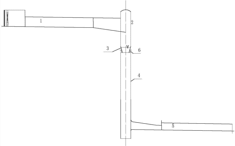
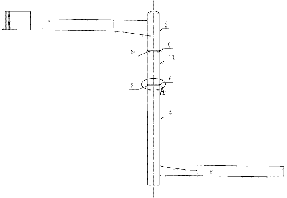
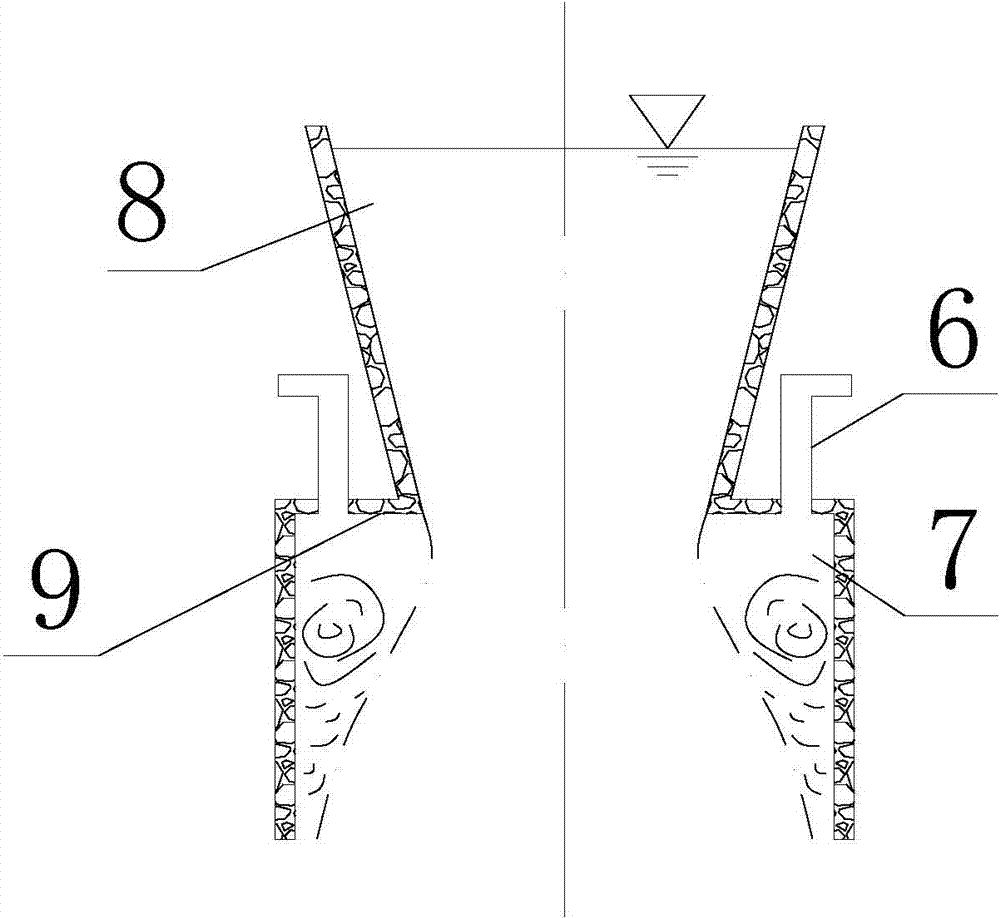
[0021] The multi-stage water cushion swirl shaft flood discharge tunnel with high water head described in this embodiment is used in hydropower projects with a water head height of 120 meters, and its structure is as follows figure 2 , 3 As shown, it includes the upper flat section 1, the vortex chamber section 2, the contraction section 3, the shaft section 4 and the lower flat section 5, and an energy-dissipating water cushion device is installed at the position where the water velocity of the shaft section 4 is 30m / s. The energy-dissipating water cushion device is composed of a contraction section 3, a sudden expansion ring plate 9 and a straight section joint 10, the contraction slope of the contraction section is 1:3, the inner ring edge of the sudden expansion ring plate is connected with the lower end of the contraction section, and the outer ring The edge is connected with the upper end of the straight section joint, and two ventilation holes 6 for connecting the blin...

Embodiment 2

[0023] The multi-stage water cushion swirl shaft flood discharge tunnel with high water head described in this embodiment is used in hydropower projects with a water head height of 150 meters, and its structure is as follows figure 2 , 3 As shown, it includes the upper flat section 1, the vortex chamber section 2, the contraction section 3, the shaft section 4 and the lower flat section 5, and an energy dissipation water cushion device is installed at the position where the water velocity of the shaft section 4 is 35m / s. The energy dissipation water cushion device is composed of a contraction section 3, a sudden expansion ring plate 9 and a straight section joint 10, the contraction slope of the contraction section is 1:0.5, the inner ring edge of the sudden expansion ring plate is connected with the lower end of the contraction section, and the outer ring The edge is connected with the upper end of the joint of the straight tube section, and four ventilation holes 6 for conn...


PUM


Abstract

The invention discloses a multistage water cushion rotational flow vertical shaft flood discharging tunnel suitable for a high water head. The multistage water cushion rotational flow vertical shaft flood discharging tunnel comprises an upper horizontal section, a volute chamber section, a contraction section, a vertical shaft section and a lower horizontal section. An energy dissipation water cushion device is arranged at the position of the vertical shaft section with the water flow speed of 30-35m / s and formed by the contraction section, a protruded expanded ring plate and a straight drum section. The inner ring edge of the protruded expanded ring plate is connected with the lower end of the contraction section, the outer ring edge is connected with the upper end of the straight drum section, vent holes communicated with a blind area and outside atmosphere are arranged at the position of the water flow blind area formed by connecting the straight drum section with the protruded expanded ring plate so that air can be aerated into water flow, and the water flow can flow through the contraction section to be annularly contracted to solid water flow due to the inner diameter of the lower end of the contraction section so as to form a water cushion on the contraction section. The rotational flow vertical shaft flood discharging tunnel is suitable for high water head hydropower engineering and can greatly improve energy dissipation efficiency, vertical shaft cavitation damage can be effectively avoided, energy dissipation pressure of the bottom water cushion can be reduced simultaneously, and bottom plate damage is avoided.

Description

technical field [0001] The invention belongs to the technical field of energy dissipation and anti-corrosion in water conservancy projects, and relates to a swirl shaft flood discharge tunnel, in particular to a multi-stage water cushion swirl shaft flood discharge tunnel suitable for high water heads. Background technique [0002] As a relatively new type of energy dissipation engineering facility, swirl shaft flood discharge tunnel has been used in water conservancy and hydropower projects with relatively low water head, especially because of its flexibility in turning, it has become more and more popular. In recent years, it has gradually The trend of popularization and application to high head water conservancy and hydropower projects. However, when vertical shaft swirl flood discharge tunnels are used in high water head hydropower stations, since the energy lost along the shaft wall is much smaller than the energy brought by the height difference, the water flow velocit...

Claims


Application Information

Patent Timeline
Patent Type & Authority Applications(China)
IPC IPC(8): E02B8/06
Inventor 邓军田忠张法星许唯临刘善均王韦张建民曲景学周茂林刘文
Owner SICHUAN UNIV
Why Eureka
Try Eureka