Built-in clutch and gear shifting control mechanism thereof

A synchronizer, built-in technology, applied in the direction of clutches, couplings, mechanical equipment, etc., can solve the problems of occupying axial space, increasing the axial size of the transmission, increasing the volume and weight of the transmission, and achieving an increase in transmission gear pairs. The effect of improving the smoothness of gear shifting, reducing volume and weight

Inactive Publication Date: 2014-04-30
赵良红
View PDF6 Cites 7 Cited by
  • Summary
  • Abstract
  • Description
  • Claims
  • Application Information

AI Technical Summary

Problems solved by technology

The currently used synchronizer will occupy a part of the axial space, making the axial size of the transmission larger, which will affect the layout of the engine and transmission, especially for cars with a transverse engine and front-wheel drive
If the number of gears is increased without increasing the number of transmission shafts, the axial dimension of the transmission will increase; if the number of gears is increased without increasing the number of transmission shafts, the radial dimension of the transmission will increase, which means Both results will increase the volume and weight of the transmission. Therefore, the number of gears in the transmission of the front-wheel-drive car with the transverse engine is not large, which makes the power and economy of the car unsatisfactory, and the smoothness of the transmission shift is poor.

Method used


Image

  • Built-in clutch and gear shifting control mechanism thereof
  • Built-in clutch and gear shifting control mechanism thereof
  • Built-in clutch and gear shifting control mechanism thereof

Examples


no. 1 example

[0032] like Figure 4 Shown is a schematic diagram of an example of installing an internal synchronizer in a five-speed manual transmission or an automatic mechanical transmission (abbreviated as AMT) gear shifting mechanism. This example consists of three shafts (input shaft 26, output shaft 20 and reverse gear shaft 25), three synchronizers (reverse gear and first gear synchronizer 21, second gear and third gear synchronizer 22 and fourth gear and fifth gear synchronizer 24) And gearshift operating mechanism 23 forms.

[0033] Reverse gear and first gear synchronizer 21 and second gear and third gear synchronizer 22 are arranged on the output shaft 20 , and fourth gear and fifth gear synchronizer 24 are arranged on the input shaft 26 . The shift operation mechanism 23 is partly arranged outside the input shaft and the output shaft.

[0034] When a certain gear is required to transmit power, the gear shift mechanism engages the synchronizer of the corresponding gear to real...

no. 2 example

[0036] like Figure 5Shown is an example of a built-in synchronizer installed in an eight-speed dual-clutch automatic transmission gear shifting mechanism. This example provides the operating force of the synchronizer by hydraulic force. It consists of four shafts (first input shaft 40, second input shaft 43, output shaft 31 and reverse gear shaft 35), five synchronizers (first gear, third gear synchronizer 36, second gear and fourth gear synchronizer 32, fifth gear and seventh gear). Gear synchronizer 38, sixth gear eighth gear synchronizer 41 and reverse gear synchronizer 34) and five shift control pistons (first gear third gear shift control piston 37, second gear fourth gear shift control piston 30, fifth gear seventh It is composed of gear shift control piston 39, sixth gear and eighth gear shift control piston 42 and reverse gear shift control piston 33).

[0037] The first-gear third-gear synchronizer 36 , the second-gear fourth-gear synchronizer 32 and the reverse-ge...

no. 3 example

[0040] like Image 6 Shown is an example of installing a built-in synchronizer in an eleven-speed dual-clutch automatic transmission gear shifting mechanism. This example also provides the operating force of the synchronizer by hydraulic pressure. By seven shafts (first input shaft 59, second input shaft 58, first intermediate shaft 56, second intermediate shaft 61, first output shaft 51, second output shaft 68, and reverse gear shaft 69), six synchronous Synchronizers (first gear, third gear synchronizer 52, fifth gear, seventh gear synchronizer 53, ninth gear, eleventh gear synchronizer 60, reverse gear second gear synchronizer 66, fourth gear sixth gear synchronizer 65 and eighth gear tenth gear synchronizer 62 ) and six shift control pistons (first gear, third gear shift control piston 50, fifth gear, seventh gear shift control piston 54, ninth gear, eleventh gear shift control piston 57, reverse gear shift control piston 67, The fourth gear and sixth gear shift control ...


PUM


Abstract

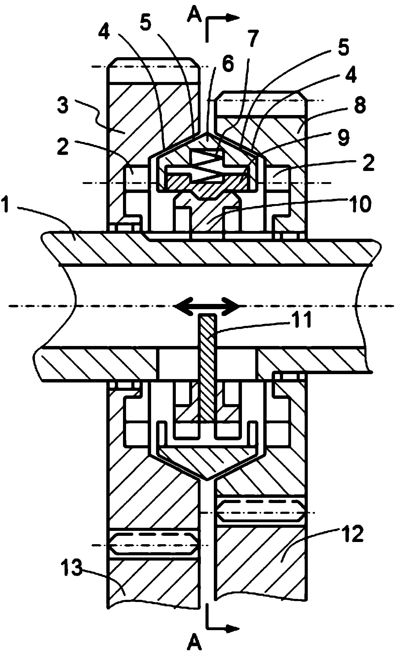
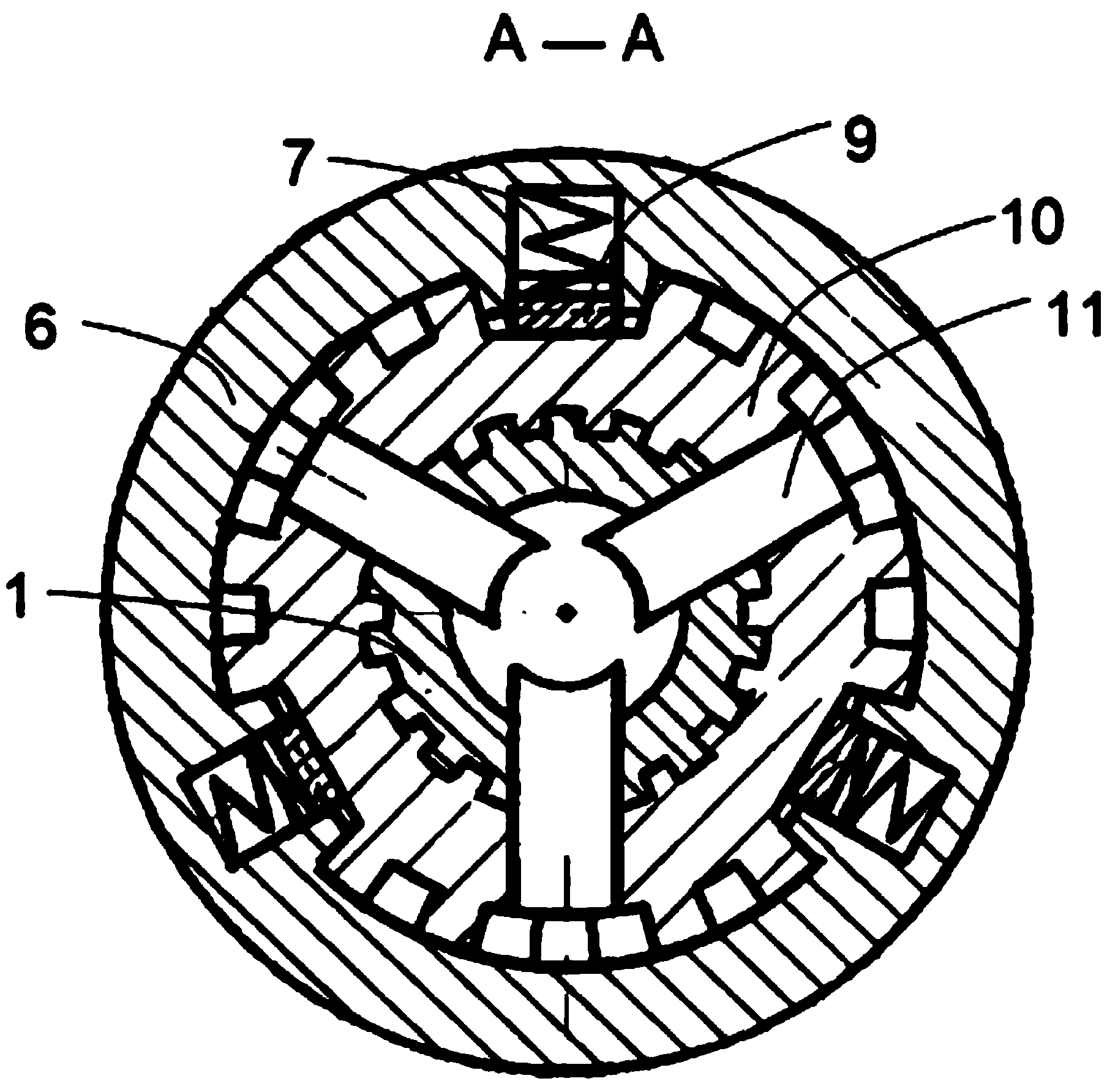
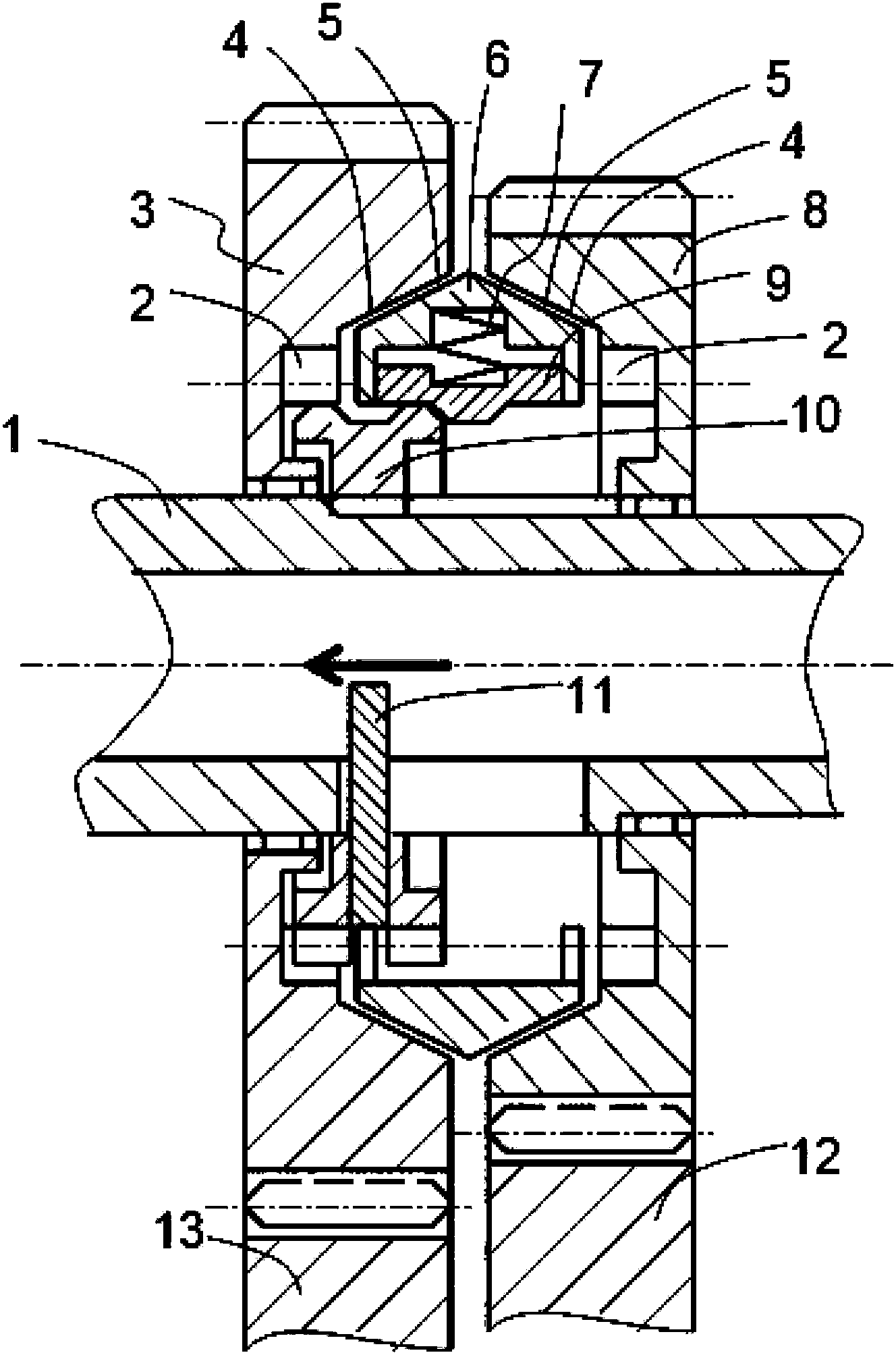
The invention discloses a built-in clutch which comprises a mounting shaft, gears, a splined hub, lifting levers and a bidirectional synchronization ring. The gears are sleeved on the mounting shaft, the splined hub is connected with the mounting shaft, cavities are arranged on the gears, inner joint gear rings are arranged on the side walls of the cavities, a hollow shaft sleeve is arranged in the mounting shaft, a slot is formed in the shaft sleeve, one end of each lifting lever is inlaid in the splined hub, the other end of each lifting lever penetrates the shot of the shaft sleeve and is inserted into an inner cavity of the shaft sleeve, an outer gear ring of the splined hub is matched with the inner joint gear rings of the gears, and the bidirectional synchronization ring is arranged among the splined hub and the side walls of the inner cavities of the gears. The built-in clutch has the advantages that the built-in clutch and a gear shifting control mechanism of the built-in clutch are based on an existing parallel shaft type gear transmission, so that gears of the transmission can be closely arranged, the axial size of the transmission can be reduced, the volume of the transmission can be decreased, the transmission can be lightened, and the manufacturing cost can be lowered.

Description

technical field [0001] The invention relates to the technical field of automobile transmissions, in particular to a novel synchronizer and a gear shifting mechanism of a parallel shaft transmission. Background technique [0002] An automotive parallel shaft transmission synchronizer is a device that engages or interrupts power between a gear or two gears. The currently used synchronizer will occupy a part of the axial space, making the axial size of the transmission larger, which affects the layout of the engine and transmission, especially for cars with the engine placed transversely and front-wheel drive. If the number of gears is increased without increasing the number of transmission shafts, the axial dimension of the transmission will increase; if the number of gears is increased without increasing the number of transmission shafts, the radial dimension of the transmission will increase, which means Both results will increase the volume and weight of the transmission. ...

Claims


Application Information

Patent Timeline
Patent Type & Authority Applications(China)
IPC IPC(8): F16D23/02F16H59/02F16H61/30F16H61/32
CPCF16D23/06F16D2023/0618F16D2300/24F16H63/30F16H63/3023F16H63/304F16H2063/3053F16H2063/3073F16H2063/3093F16D23/02F16D23/04
Inventor 赵良红
Owner 赵良红
Why Eureka
Try Eureka