
Derating control method for permanent magnet synchronous motor

A technology of permanent magnet synchronous motor and control method, which is applied in the direction of speed/torque control of a single motor, and can solve problems such as system performance limitations

Active Publication Date: 2014-04-30
UNITED AUTOMOTIVE ELECTRONICS SYST
View PDF7 Cites 15 Cited by
  • Summary
  • Abstract
  • Description
  • Claims
  • Application Information

AI Technical Summary

Problems solved by technology

The existing derating control method adopts a "one size fits all" control method at all speeds, which will cause the performance of the system to be limited when the rotor temperature is high

Method used


Image

  • Derating control method for permanent magnet synchronous motor
  • Derating control method for permanent magnet synchronous motor
  • Derating control method for permanent magnet synchronous motor

Examples


Embodiment Construction

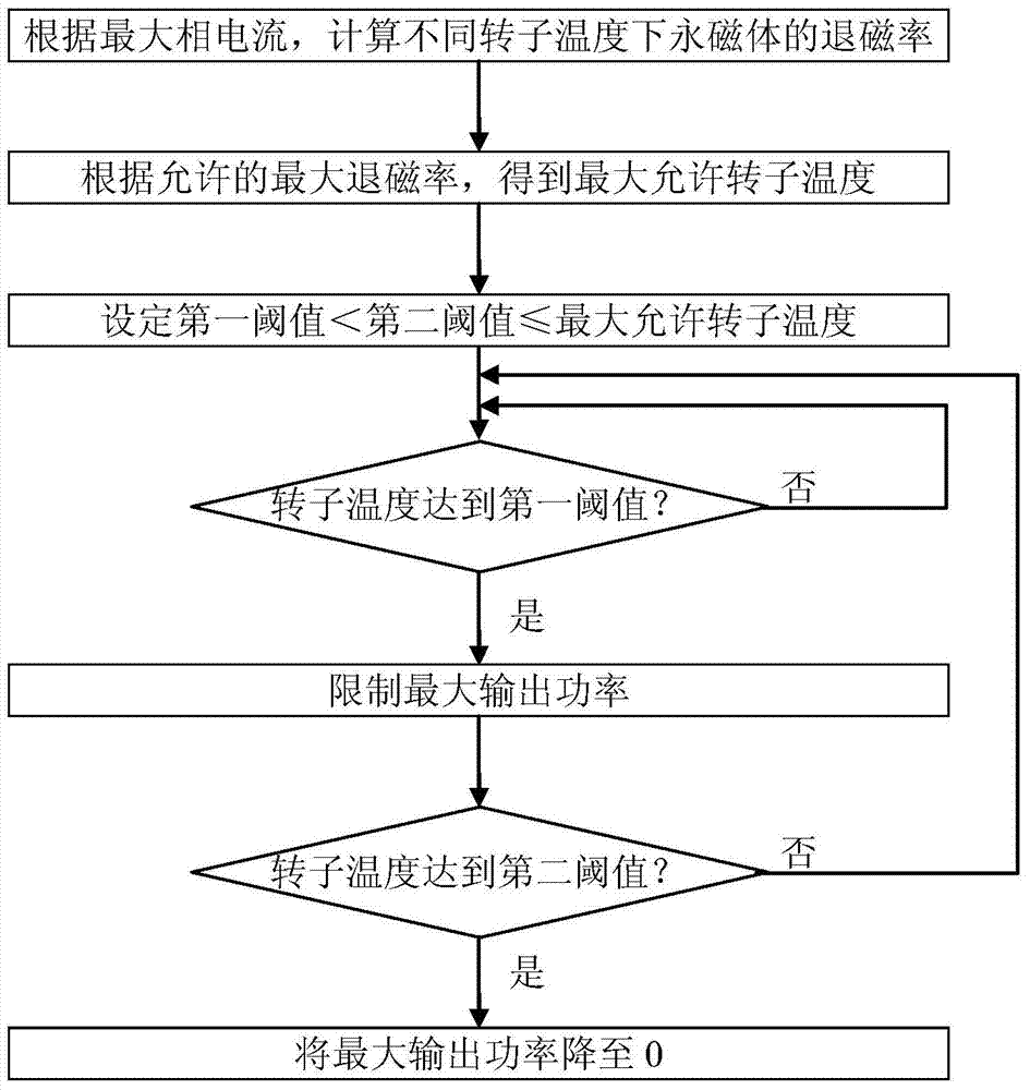
[0036] see Figure 5 , the derating control method of the permanent magnet synchronous motor of the present application comprises the following steps:

[0037] In the first step, the permanent magnet synchronous motor is simulated from the normal working mode to the failure response mode. Each simulation is based on the different output speed of the permanent magnet synchronous motor, but always maintains the maximum output torque under the speed condition. Record the instantaneous peak current at each rotational speed.

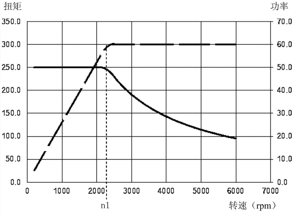
[0038] This kind of simulation can be a transient current simulation in the form of software, which is carried out on the circuit model of the built motor drive system, mainly to simulate the transient change of the three-phase current of the motor when the mode is switched; it can also be a simulation of the actual motor drive system test measurement. see Figure 6, when the permanent magnet synchronous motor switches from the normal working mode (such as...


PUM


Abstract

The invention discloses a derating control method for a permanent magnet synchronous motor. The method includes the first step of recording the instantaneous peak current of the permanent magnet synchronous motor from a normal working mode to an invalid response mode under the conditions of different rotation speeds and constant maximum torque, the second step of recording degaussing rates at different rotor temperatures according to the instantaneous peak current at each rotation speed, the third step of obtaining the maximum allowable rotor temperature at each rotation speed according to the maximum allowable degaussing rate, the fourth step of setting derating coefficients for each rotation speed and each rotor temperature, and the fifth step of limiting the maximum output torque and the maximum output power according to the derating coefficients set at the fourth step and the current rotation speed and rotor temperature. The derating control method is especially suitable for the permanent magnet synchronous motors on new energy automobiles, can ensure that the residual magnetic flux density of permanent magnets does not exceed a certain scope and can meet the requirements for climbing at low speed and overtaking at high speed.

Description

technical field [0001] The present application relates to a derating control method of a permanent magnet synchronous motor on a new energy vehicle. Background technique [0002] Permanent magnet synchronous motors are widely used in new energy vehicles (pure electric vehicles, hybrid vehicles, etc.) as drive motors. The rotor of the permanent magnet synchronous motor is equipped with permanent magnets, usually magnetic steel, and its main characteristic parameters include residual magnetic flux density (Br) and intrinsic coercive force (Hcj). [0003] The residual flux density determines the performance of the permanent magnet, which in turn affects the output torque and power of the permanent magnet synchronous motor. The phenomenon in which the residual magnetic flux density of a permanent magnet decreases is called demagnetization, and the ratio of the reduction in residual magnetic flux density to the original residual magnetic flux density is called a demagnetization ...

Claims


Application Information

Patent Timeline
IPC IPC(8): H02P6/06
Inventor 王萑何海徐玮陈剑锋
Owner UNITED AUTOMOTIVE ELECTRONICS SYST
Learn More