
Adhesive composition for optical applications, adhesive layer for optical applications, optical member, polarizing plate, and image display device

A technology of adhesive layer and adhesive, which is applied in the direction of optical elements, adhesive types, ester copolymer adhesives, etc., which can solve the problem of peeling of optical components, low compatibility, and reduced adhesion at the interface of adherends and other problems to achieve the effect of suppressing uneven brightness

Active Publication Date: 2014-04-30
NITTO DENKO CORP
View PDF13 Cites 2 Cited by
  • Summary
  • Abstract
  • Description
  • Claims
  • Application Information

AI Technical Summary

Problems solved by technology

However, when the adhesive is made highly elastic, the adhesive force at the interface of the adherend decreases, and there is a problem that the peeling of the optical member is likely to occur under heating and humidification.
[0004] Hitherto, for example, as adhesives with high peel resistance, photopolymers containing modified (meth)acrylic graft polymers obtained by graft-polymerizing chains containing cyclic ether group-containing monomers have been proposed. Curable adhesive (Patent Document 1) may have a problem of low compatibility depending on the application

Method used


Image

  • Adhesive composition for optical applications, adhesive layer for optical applications, optical member, polarizing plate, and image display device

Examples


Embodiment 1

[0219] (Preparation of Acrylic Polymer)

[0220] Add 85 parts by weight of n-butyl acrylate (BA), 15 parts by weight of methoxyethyl acrylate (MEA) together with 200 parts by weight of ethyl acetate in a four-necked flask equipped with a stirring blade, a thermometer, a nitrogen inlet tube, and a condenser. ), 3 parts by weight of 4-hydroxybutyl acrylate (HBA), 0.1 parts by weight of 2,2'-azobisisobutyronitrile as a polymerization initiator, introducing nitrogen while stirring slowly, and replacing the flask with nitrogen for 1 hour The temperature of the liquid inside was kept at around 55° C. and the polymerization reaction was carried out for 10 hours to prepare an acrylic polymer solution with a weight average molecular weight of 900,000. The glass transition temperature of the obtained acrylic polymer was 233K.

[0221] (Preparation of graft polymer)

[0222] The obtained acrylic polymer solution was diluted with ethyl acetate so that the solid content would be 25%, to ...

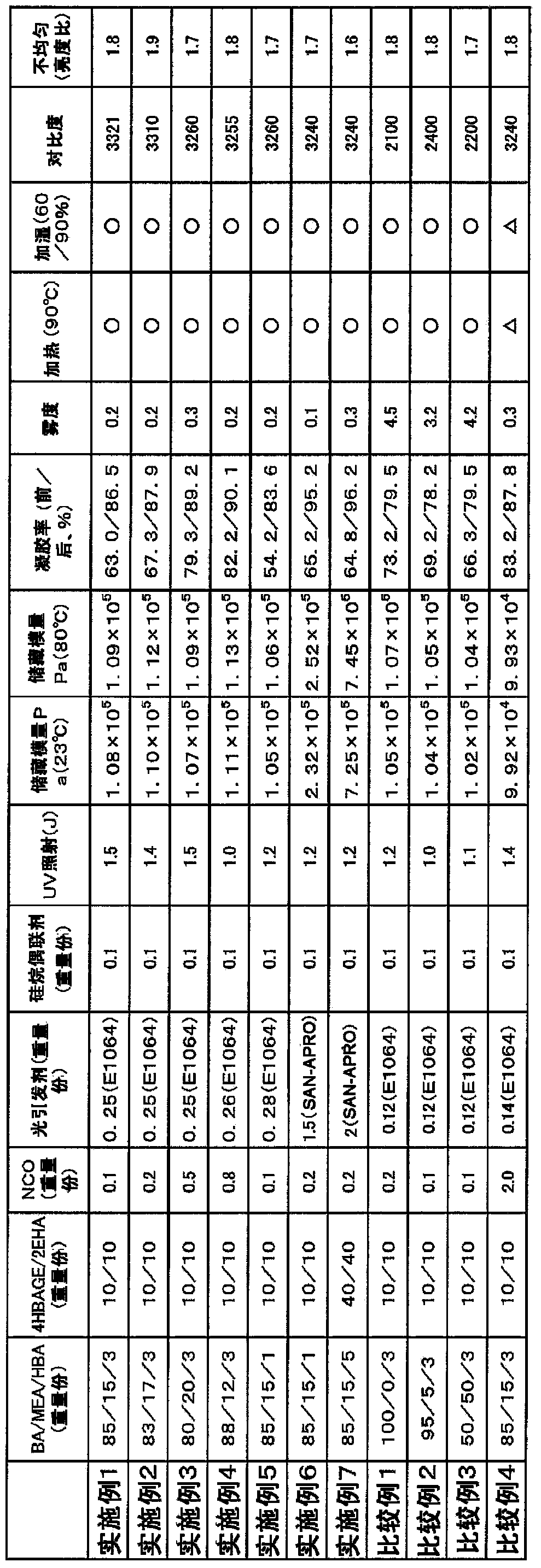
Embodiment 2~7、 comparative example 1~4

[0231] In the same manner as in Example 1, according to the compositions described in Table 1, Examples 2 to 7 and Comparative Examples 1 to 4 were prepared for adhesive layers and polarizing plate samples with adhesive.

[0232] Table 1 shows the evaluation results of the samples obtained in the above Examples and Comparative Examples.

[0233] [Table 1]

[0234]


PUM

PropertyMeasurementUnit
thicknessaaaaaaaaaa
thicknessaaaaaaaaaa
thicknessaaaaaaaaaa

Abstract

The purpose of the present invention is to provide: an adhesive composition for optical applications, which is capable of suppressing luminance unevenness without deteriorating the contrast characteristics in optical applications, and which can be used for optical members and prevents the optical members from separation in a reliability test; an adhesive layer; an optical member; an image display device and the like. An adhesive composition for optical applications, which contains 100 parts by weight of a modified (meth)acrylic graft polymer and 0.01-1.80 parts by weight of an isocyanate crosslinking agent, is prepared. The modified (meth)acrylic graft polymer is obtained by graft polymerizing chains, each of which contains a cyclic ether group-containing monomer, to the trunk polymer, and contains, as constituent components, an alkyl (meth)acrylate, a cyclic ether group-containing monomer, and a non-cyclic ether group-containing monomer. The modified (meth)acrylic graft polymer contains 8-40 parts by weight of the non-cyclic ether group-containing monomer per 100 parts by weight of the total of other monomer components that constitute the trunk polymer. An adhesive layer for optical applications, which is formed from the composition, an optical member, an image display device and the like are also produced.

Description

technical field [0001] The present invention relates to an adhesive composition for an optical member, an adhesive layer, an optical member provided with an adhesive layer, a polarizing plate provided with an adhesive layer, and an optical member provided with the adhesive layer. An image display device of an optical member. Background technique [0002] Optical members used in liquid crystal display devices, such as polarizing plates, retardation plates, and the like, are attached to liquid crystal cells using adhesives. After exposing the liquid crystal display device to heating and humidification for a certain period of time, when the backlight is turned on to display in black, there is a problem that brightness unevenness occurs and visibility decreases. This is considered to be because the polarizing plate shrinks due to the heat of the backlight during liquid crystal display, and thus the axial shift of the polarizing plate due to the shrinkage, and the axial shift of...

Claims


Application Information

Patent Timeline
Patent Type & Authority Applications(China)
IPC IPC(8): C09J151/00C09J7/02C09J133/04
CPCC09J133/04C09J7/02C09J151/003C08F265/06C09J7/385Y10T428/2809Y10T428/2826Y10T428/2891Y10T428/2848C08F220/1808C08F216/1416C08F230/085C08F220/18C08F220/325C08F220/32C09J151/00G02B1/14G02B1/04G02B5/305
Inventor 东昌嗣诸石裕藤田茂井上彻雄
Owner NITTO DENKO CORP
Learn More