Blood bag aseptic connection method and equipment used in the method

A blood bag and equipment technology, applied in the field of medical equipment, can solve the problem of large waste of sterile connection equipment, and achieve the effect of data processing and remote data processing improvement, stability improvement, and operation efficiency improvement.

Active Publication Date: 2015-08-19
WUHAN BMS MEDICALTECH
View PDF11 Cites 0 Cited by
  • Summary
  • Abstract
  • Description
  • Claims
  • Application Information

AI Technical Summary

Problems solved by technology

[0006] The technical problem to be solved by the present invention is to provide a blood bag aseptic connection method and equipment for cutting and connecting blood bag tubes using composite metal wires instead of cutting sheets. The method has simple steps and is easy to implement. , and can solve the problem of large waste of existing aseptic connection equipment

Method used


Image

  • Blood bag aseptic connection method and equipment used in the method
  • Blood bag aseptic connection method and equipment used in the method
  • Blood bag aseptic connection method and equipment used in the method

Examples


Embodiment 1

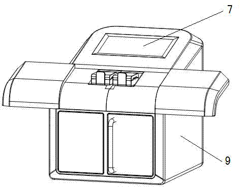
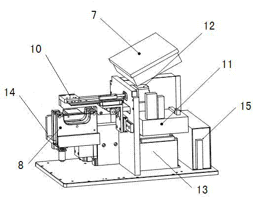
[0038] Such as Figure 1-Figure 7 As shown, a blood bag aseptic connecting device includes 2 power supplies 15, 5 motors 12, 5 motor drivers 13, PLC controller 11, 2 blood vessel clips 10, 1 wire box 8 and 1 Touch screen 7; wherein one power supply 15 supplies power for 5 motors 12, 5 motor drivers 13, PLC controller 11 and 1 touch screen 7, and another power supply 15 is connected with the composite metal wire 4 of wire box 8, for Composite wire 4 provides current; the first motor 12 controls the horizontal movement of the first vascular clamp 10, the second motor 12 controls the horizontal movement of the second vascular clamp 10, and the third motor 12 controls the reel of the wire box 8 scrolling, the fourth motor 12 controls the up and down movement of the wire box 8, and the fifth motor 12 controls the forward and backward movement of the second vascular clamp 10; the five motors 12 are respectively connected to the PLC controller 11 through five motor drivers 13 ; The ...

Embodiment 2

[0051] The difference from Embodiment 1 is that the touch screen 7 of the blood bag aseptic connection device adopts a 7-inch touch color screen, and the 7-inch touch color screen is connected to a remote server for data transmission and control .

[0052] The difference from Example 1 is: in step 1) of the blood bag aseptic connection method, the two blood vessel clamps move 4mm in opposite directions at the same time; in step 3), the blood bag aseptic connection device line The box continues to rise by 2mm; in step 4), the two vascular clips move 4mm toward each other; in step 5), the two vascular clips move 3mm toward each other; °C, the time for the composite metal wire to cut the blood bag tube is 1 second.

[0053] In step 3) of this embodiment, after the composite metal wire 4 cuts the blood bag tube, the wire box 8 of the blood bag aseptic connection device continues to rise for 2mm and stops there; at the same time, the second blood vessel clamp is displaced in the f...


PUM


Abstract

Disclosed are a blood bag sterile connection method and a device used in the method. The device comprises a motor (12), a junction box (1), a PLC controller (11) and two vascular clamps (10). The junction box (1) is provided inside with a left scroll (3-1) and a right scroll (3-2), wherein a composite metal wire (4) on the left scroll (3-1) is connected with the right scroll (3-2). The method comprises the steps of: 1) placing blood bag pipes above the junction box (1), clamping a position to be cut using the vascular clamps (10) and simultaneously moving the two vascular clamps (10) in opposite directions; 2) heating the composite metal wire (4) and cutting the blood bag pipes using the composite metal wire (4); 3) after completing cutting, aligning the blood bag pipes to be connected; 4) moving the two vascular clamps (10) towards each other, rolling away the used composite metal wire (4) and rolling out a new composite metal wire (4); 5) connecting the blood bag pipes by heating the composite metal wire (4) and simultaneously moving the two vascular clamps (10) towards each other; and 6) returning the junction box (1) to the initial position, taking out the connected blood bag pipes and returning the vascular clamps (10) to the initial position.

Description

technical field [0001] The invention belongs to the field of medical equipment, and in particular relates to a blood bag aseptic connection method and equipment used therefor. The method and device are used for cutting and connection of blood bag tubes. Background technique [0002] At present, the traditional cutting sheet is used to cut and connect the blood bag tube. The cutting method of the cutting sheet is easy to realize, and the heat carried by the cutting sheet itself is large, which is easy to melt the blood bag tube. However, it is precisely because of the conventional cutting sheet It carries a lot of heat. During the connection process, the blood bag tubes undergo chemical changes and are thermally fused together. The excess heat of the cutting piece is actually a waste of energy, and the blood bag tubes absorb too much heat and it is easy to make the chemical change time Too long, it is not a reliable choice for clinical medicine. [0003] Due to the reason wh...

Claims


Application Information

Patent Timeline
Patent Type & Authority Patents(China)
IPC IPC(8): A61B17/00
CPCB29C65/24A61M39/18A61M1/02B29C65/2038B29C65/2046B29C65/222B29C66/0018B29C66/1142B29C66/5221B29C66/7373B29C66/8167B29C66/857B29C66/919B29C66/949B29L2031/7148A61J1/10
Inventor 何俊
Owner WUHAN BMS MEDICALTECH
Why Eureka
Try Eureka