A photoresist recovery system

A recovery system and photoresist technology, which is applied to the surface coating liquid device, coating, etc., can solve the problems of coating photoresist waste and reduce production costs, and achieve the goal of reducing waste and production costs Effect

Inactive Publication Date: 2016-08-17
BEIJING BOE DISPLAY TECH CO LTD +1
View PDF6 Cites 0 Cited by
  • Summary
  • Abstract
  • Description
  • Claims
  • Application Information

AI Technical Summary

Problems solved by technology

[0003] The purpose of the present invention is to provide a photoresist recovery system, which is used to solve the problem of a large amount of waste when coating photoresist in the current production process of color filter substrates and array substrates, thereby reducing production costs

Method used


Image

  • A photoresist recovery system
  • A photoresist recovery system
  • A photoresist recovery system

Examples


Embodiment Construction

[0027] The implementation process of the embodiment of the present invention will be described in detail below in conjunction with the accompanying drawings. It should be noted that the same or similar reference numerals represent the same or similar elements or elements having the same or similar functions throughout. The embodiments described below by referring to the figures are exemplary only for explaining the present invention and should not be construed as limiting the present invention.

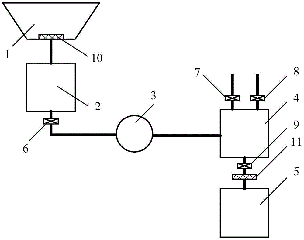
[0028] see figure 1 , an embodiment of the present invention provides a photoresist recovery system, including:

[0029] The receiving device 1 is connected with the photoresist coating device and used for receiving the used photoresist discharged from the photoresist coating device. Since the photoresist coating device is divided into a spin coating method and a slit coating method, the receiving device 1 needs to be adaptively adjusted according to the equipment of the above two c...


PUM


Abstract

The invention discloses a photoresist recovering system which is used for solving the problems that the used photoresist exhausted from a photoresist coating machine is wasted. The system comprises a receiving device which is connected with the photoresist coating device, and a conveying device connected with a first buffer device and a second buffer device, respectively, and is used for conveying the photoresist in the first buffer device into the second buffer device, wherein the top of the second buffer device is connected with a dry and clean air source via a pipeline which is provided with a second control valve; the bottom of the second buffer device is connected with a pipeline which is provided with a fourth control valve; the second buffer device is used for containing the used photoresist conveyed by the conveying device and conveying the used photoresist to a photoresist barrel via the pipeline provided with the fourth control valve under the air pressure provided by the dry and clean air source. The used photoresist exhausted from the photoresist coating machine enters the photoresist barrel via the devices, in this way, the photoresist can be recycled, and consequently, the production cost is reduced.

Description

technical field [0001] The invention relates to the technical field of display devices, in particular to a photoresist recovery system. Background technique [0002] In the photolithography process of making color filter substrates and array substrates, the photoresist is mainly diluted to a certain concentration by adding a diluent to the photoresist, and then spin coating (Spin coat) or slit coating Slit coat method, the diluted photoresist is evenly coated on the substrate. In order to coat the photoresist evenly on the substrate, the spin coating method usually first coats a large amount of photoresist on the substrate, and then rotates the substrate so that the photoresist can be evenly coated on the entire substrate. In this coating method, the utilization rate of photoresist is low, and most of the photoresist is discharged into the waste liquid tank during the spin coating process; while in the slit coating method, the working table is The upper coated substrate is...

Claims


Application Information

Patent Timeline
Patent Type & Authority Patents(China)
IPC IPC(8): B05C11/10
Inventor 陈鹏杜宏伟吴凯民肖金涛齐鹏煜孙培会
Owner BEIJING BOE DISPLAY TECH CO LTD
Why Eureka
Try Eureka