
Automotive double-fan three-level speed control circuit and control method

A three-stage speed regulation and control circuit technology, which is applied in the control of coolant flow, engine components, machines/engines, etc., can solve the problems of inability to adjust the voltage, the working voltage cannot be changed, and the noise is large, so as to reduce the use of power, Easy to popularize and use, reduce the effect of fan noise

Active Publication Date: 2014-05-07
CHONGQING CHANGAN AUTOMOBILE CO LTD
View PDF6 Cites 13 Cited by
  • Summary
  • Abstract
  • Description
  • Claims
  • Application Information

AI Technical Summary

Problems solved by technology

Neither method can adjust the voltage (that is, the operating voltage of the dual fans cannot be changed). Under certain working conditions (such as when the engine temperature is not particularly high), it will consume more power if the dual fans are operated at high speed. At the same time, the noise of the fan operation is relatively large (the noise of the fan is related to the speed of the fan, the higher the speed, the greater the noise), which will affect the comfort of the vehicle

Method used


Image

  • Automotive double-fan three-level speed control circuit and control method
  • Automotive double-fan three-level speed control circuit and control method
  • Automotive double-fan three-level speed control circuit and control method

Examples


Embodiment Construction

[0025] The present invention will be further described below in conjunction with accompanying drawing.

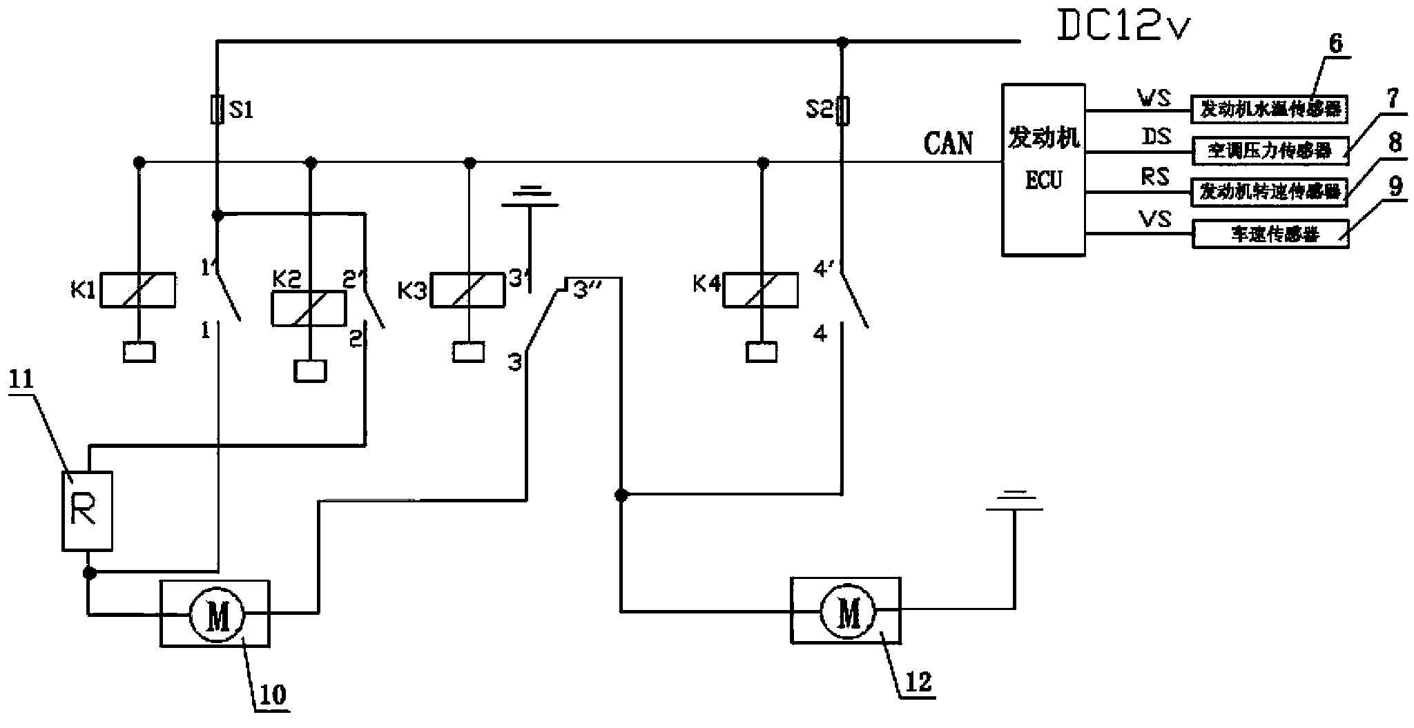
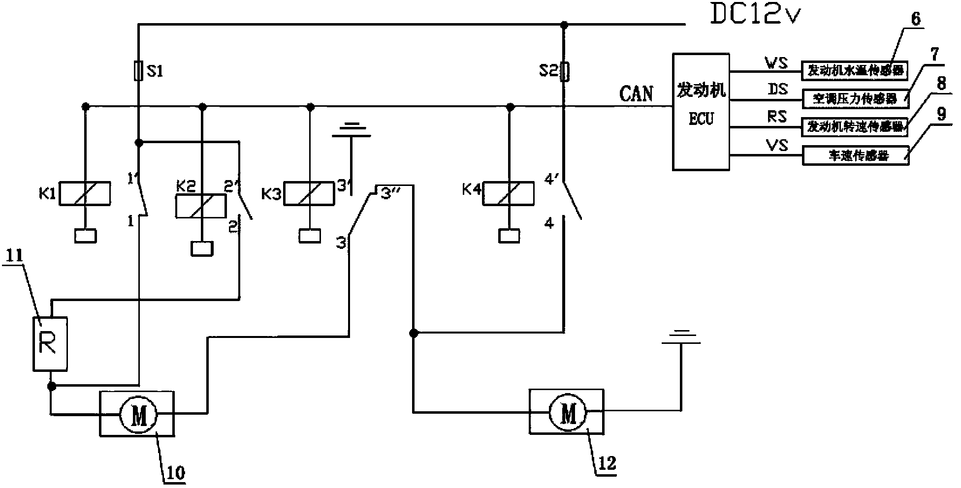
[0026] Such as Figure 1 to Figure 6 The three-stage speed regulation control circuit for automobile dual fans shown includes relays K1, K2, K3, K4, a first electronic fan 10, a second electronic fan 12, an engine ECU and an adjustable resistor 11, and the power of the first electronic fan 10 Greater than the power of the second electronic fan 12, the input end of the engine ECU is connected with the engine water temperature sensor 6, the air conditioner pressure sensor 7, the engine speed sensor 8 and the vehicle speed sensor 9, so as to obtain the engine water temperature signal WS, the air conditioner pressure signal DS, and the engine speed sensor in real time. Signal RS and vehicle speed signal VS, the output of the engine ECU is connected to the coils of relays K1, K2, K3, and K4 through the CAN bus, and the relays K1, K2, K3, and K4 are controlled to be turned on / off...


PUM


Abstract

The invention discloses an automotive double-fan three-level speed control circuit and a control method. The automotive double-fan three-level speed control circuit comprises relays, a first electric fan, a second electric fan, an engine ECU (Electronic Control Unit) and an adjustable resistor; an input end of the engine ECU obtains motor water temperature signals, air conditioner pressure signals, motor rotating speed signals and vehicle speed signals in real time; an output end of the engine ECU is connected with coils of the relays K1, K2, K3 and K4 through a CAN (Controller Area Network) bus to control conduction or disconnection of the relays K1, K2, K3 and K4; the first electric fan is connected with the second electric fan in a series mode to achieve low speed control; the first electric fan which is connected with the adjustable resistor in a series mode is connected with the second electric fan in a parallel mode to achieve intermediate speed control; the first electric fan is connected with the second electric fan in a parallel mode to achieve high speed control. Under some specific working condition, the noise value of fan operation is reduced through the intermediate speed control mode meanwhile temperature reducing is satisfied and meanwhile the service power of the fans is reduced.

Description

technical field [0001] The invention belongs to the technical field of automobile engine cooling, and in particular relates to an automobile dual-fan three-stage speed regulation control circuit and a control method. Background technique [0002] The cooling system of automobile engine cooling generally adopts electronic fan, which relies on the motor to drive the fan to work; with the continuous improvement of engine technology, the engine power continues to increase, resulting in an increasing heat dissipation of the engine. Under the limited layout space of the engine room, It is more and more common to rely on increasing the fan air volume to solve the problem of high water temperature. [0003] At present, people use dual electronic fans to cool down, so that the dual electronic fans can work at low speed or high speed according to actual needs. Speed ​​or PWM speed regulation, among which PWM speed regulation is more costly, and it is only used in high-end models at t...

Claims


Application Information

Patent Timeline
Patent Type & Authority Applications(China)
IPC IPC(8): F01P7/12
Inventor 李阳周奕王平忠张玲唐连海韩晓晨赵勤于美玲
Owner CHONGQING CHANGAN AUTOMOBILE CO LTD
Learn More