A wind power generation system that relies on steel structure composite towers to provide stable power

A technology for wind power generation system and stable power supply, which is applied in the direction of wind power generators storing gravitational potential energy, wind power generation, installation/supporting wind power motor configuration, etc. Problems such as battery and lithium battery pollution, difficult air tightness testing, etc., to solve the problem of unstable power supply, facilitate maintenance and debugging, and improve load-carrying performance

Inactive Publication Date: 2017-02-15
NORTH CHINA UNIV OF WATER RESOURCES & ELECTRIC POWER
View PDF8 Cites 1 Cited by
  • Summary
  • Abstract
  • Description
  • Claims
  • Application Information

AI Technical Summary

Problems solved by technology

[0002] The biggest disadvantage of wind power generation in the prior art is that the power source is unstable and greatly affected by the weather. There is power when there is wind, and no power when there is no wind. The power is sufficient when the wind is strong, and the power is weak when the wind is small, which has an impact on the power grid. It is relatively large, and it is not a high-quality power source for the current power grid. It can only be used as a supplementary power source and cannot be used as a main power source. In order to solve this problem, some people use batteries to adjust to achieve stable power supply. It is proposed that lithium batteries, which are widely popular in recent years, are seriously polluted in the manufacturing process of lead-acid batteries and lithium batteries, and both are limited by the life of charge and discharge times, and need to be replaced regularly, so that both social benefits and economic costs are not feasible
[0003] In the existing power grid, there is also pumped water storage, which needs to be installed near the water source, and infrastructure such as dams needs to be built, the investment cost is high, and there are specific requirements for the external environmental conditions; There is a method of using air compressors for energy storage, using the underground tunnels of some abandoned mines as gas storage chambers to store compressed air. These abandoned mines are difficult to perform air tightness testing, so this method is specifically applied There are very few examples, indicating that the feasibility is not strong

Method used


Image

  • A wind power generation system that relies on steel structure composite towers to provide stable power
  • A wind power generation system that relies on steel structure composite towers to provide stable power
  • A wind power generation system that relies on steel structure composite towers to provide stable power

Examples


Embodiment 1

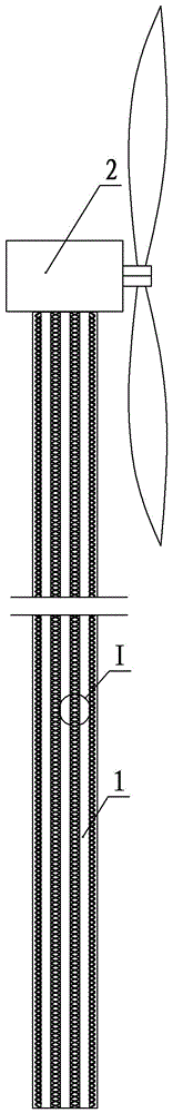
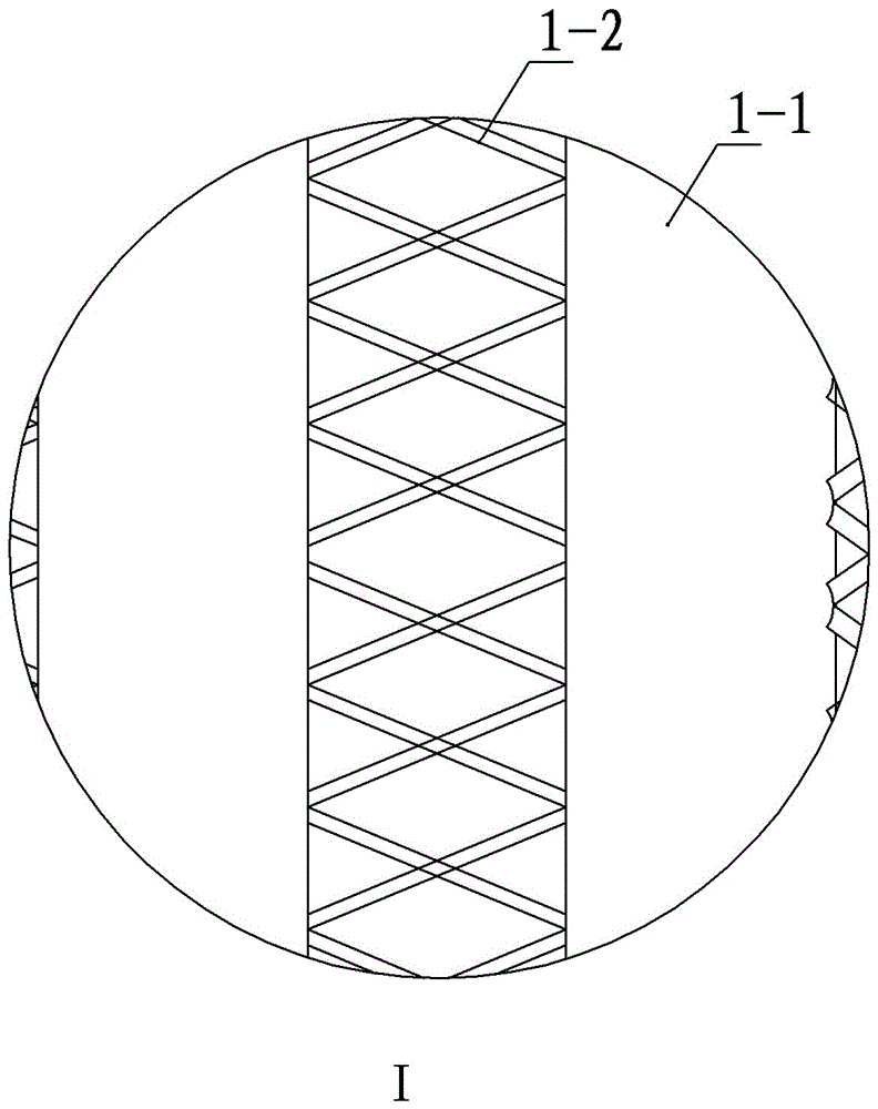
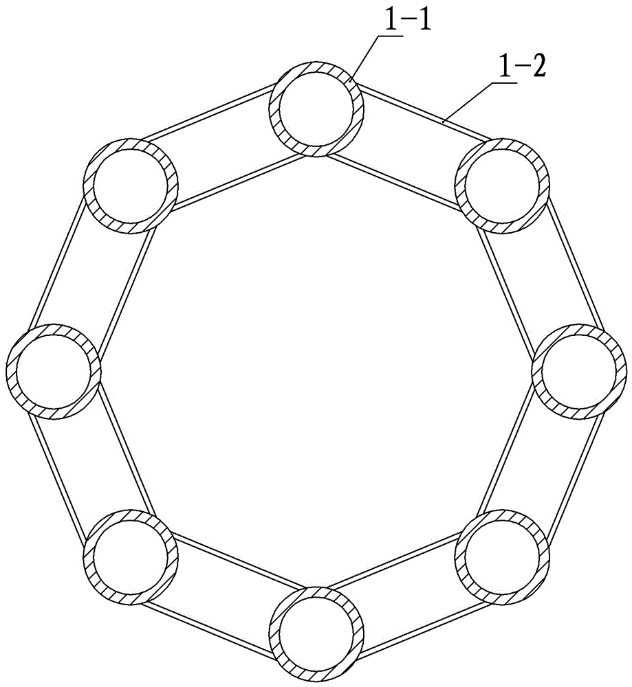
[0037] Embodiment one: see Figure 1-3 , Figure 14 , Figure 16 In the figure, a wind power generation system that relies on a steel structure composite tower to provide a stable power supply includes a fan, a tower, and a control module. The tower includes at least several elongated cylindrical pressure tanks, and the several pressure tanks Arranged around a central axis, adjacent pressure tanks are fixedly connected by steel structure trusses; the lower end of the tower body is fixed on the ground, and a fan is installed at the upper end of the tower body; several pressure tanks form a group of two Energy storage and energy release unit, liquid medium and compressed air are provided in the pressure tank of each energy storage and energy release unit, and the reversible compression device is connected between the two pressure tanks through pipelines, and each reversible compression device They are all connected to the control module, the output cables of the fan are connec...

Embodiment 2

[0044] Embodiment two: see Figure 1-2 , Figure 4 , Figure 14 , Figure 16 , Embodiment 2 is basically the same as Embodiment 1, and the similarities will not be repeated. The difference is that the cross section of the pressure tank described in Embodiment 2 is trapezoidal.

[0045] The outer surface of the tower body in Embodiment 2 may also be provided with a sun-proof and heat-insulating layer; the sun-proof and heat-insulating layer is a photovoltaic panel. It can supplement wind power generation while solving the problem that the pressure tank is afraid of high temperature exposure, such as Figure 9 As shown, this structure is also a measure that kills two birds with one stone.

Embodiment 3

[0046] Embodiment three: see Figure 1-2 , Figure 5 , Figure 14 , Figure 16 , Embodiment 3 is basically the same as Embodiment 1, and the similarities will not be repeated. The difference is that the cross-section of the pressure tank described in Embodiment 3 is square.

[0047] The outer surface of the tower body in Embodiment 3 may also be provided with a sun-proof and heat-insulating layer; the sun-proof and heat-insulating layer is a photovoltaic panel. It can supplement wind power generation while solving the problem that the pressure tank is afraid of high temperature exposure, such as Figure 10 As shown, this structure is also a measure that kills two birds with one stone.

[0048] The specific examples of the reversible fluid pump-motor and reversible motor-generator in the reversible compression device mentioned in the above three embodiments can refer to the description of the Chinese invention patent with the patent number: 201110137038.X, in which there is...


PUM


Abstract

The invention relates to a wind power generation system supplied with stabilized power supply by a steel structure compound tower body. The wind power generation system comprises a fan, the tower body and a control module, wherein the tower body at least comprises a plurality of elongated barrel pressure tanks; the pressure tanks are circumferentially arranged around a central shaft; the adjacent pressure tanks are connected through a steel structure truss or welding to form the tower body; every two pressure tanks among the pressure tanks are a group to form an energy storage and release unit; liquid medium and compressed air are arranged in the pressure tanks of each energy storage and release unit; a reversible type compression device is connected between two pressure tanks through a pipeline; each reversible type compression device is connected with the control module; an output cable of the fan is connected with the control module; each reversible type compression device is provided with an output cable; each output cable is connected with a power grid. Compared with that of a single cylindrical tower body in the prior art, the bearing performance of the steel structure compound tower body is greatly improved, the function of energy storage is realized, and double functions are achieved.

Description

technical field [0001] The invention relates to the technical field of wind power generation, in particular to a wind power generation system which relies on a steel structure composite tower body to provide stable power. Background technique [0002] The biggest disadvantage of wind power generation in the prior art is that the power source is unstable and is greatly affected by the weather. When there is wind, there is power, and when there is no wind, there is no power. When the wind is strong, the power is sufficient, and when the wind is small, the power is weak, which impacts the power grid. It is relatively large, and it is not a high-quality power source for the current power grid. It can only be used as a supplementary power source and cannot be used as a main power source. In order to solve this problem, some people use batteries to adjust to achieve stable power supply. It is proposed that lithium batteries, which are widely popular in recent years, are seriously ...

Claims


Application Information

Patent Timeline
Patent Type & Authority Patents(China)
IPC IPC(8): F03D9/17F03D13/20
CPCY02E10/72Y02E10/728Y02E60/16Y02E70/30
Inventor 魏鲁双魏群刘尚蔚胡昊任岩左智成
Owner NORTH CHINA UNIV OF WATER RESOURCES & ELECTRIC POWER
Why Eureka
Try Eureka